
Page 143 - Instrumentation Reference Book 3E
P. 143
Pressure measurement 127
the reservoir so that there is always a small by a delicate hairspring. The other end of the
hydraulic head to cause lubricant to flow into tube is open so that the pressure to be measured
the assembly. can be applied via the block to which it is fixed
Rotation of the piston in the cylinder sets up and which also carries the pressure connection
radial forces in the lubricating fluid which tend to and provides the datum for measurement of the
keep the piston centered, but the speed of rota- deflection.
tion should be constant and the drive itself should If the internal pressure exceeds the external
not impart vibration or spurious forces. This is pressure the shape of the tube changes from oval
achieved by arranging the motor to drive the towards circular with the result that it becomes
cylinder pulley via an oval drive pulley which is straighter. The movement of the free end drives
therefore alternatively accelerating and decelerat- the pointer mechanism so that the pointer moves
ing. The final drive is via the bearing on to the pin with respect to the scale. If the internal pressure is
secured to the piston plate. In this way, once the less than the external pressure, the free end of the
piston is in motion, it rotates freely until it has tube moves towards the block, causing the pointer
lost sufficient momentum for the drive bearing to to move in the opposite direction.
impart a small impulse which accelerates the pis- The material from which the tube is formed
ton. This ensures that it is rotating freely for at must have stable elastic properties and be selected
least 90 percent of the time. to suit the fluid whose pressure is to be measured.
The piston and cylinder are machined from Phosphor bronze, beryllium copper, and stainless
tungsten carbide to a tolerance of 0.1 micrometer steel are used most widely but for applications
SO that the typical clearance between them is 0.5 involving particularly corrosive fluids, alloys, such
micrometer. A balance indicator that tracks a soft as K-Monel, are used. The thickness of the tube
iron band set in the bell shows the position of the and the material from which it is to be fabricated
piston and allows fluid head corrections for the are selected according to the pressure range. but
most precise measurements. the actual dimensions of the tube determine the
The principal weights are fabricated in stainless force available to drive the pointer mechanism.
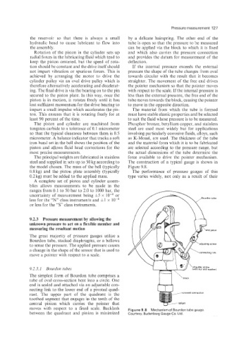
steel and supplied in sets up to 50 kg according to The construction of a typical gauge is shown in
the model chosen. The mass of the bell (typically Figure 9.8.
0.8 kg) and the piston plate assembly (typically The performance of pressure gauges of this
0.2 kg) must be added to the applied mass. type varies widely, not only as a result of their
A complete set of piston and cylinder assem-
blies allows measurements to be made in the
ranges from 0.1 to 50 bar to 2.0 to 1000 bar, the
uncertainty of measurement being 15 x or
less for the “N” class instruments and &1 x
or less for the “S” class instruments.
9.4.3 Pressure measurement by allowing the
unknown pressure to act on a flexible member and
measuring the resultant motion
The great majority of pressure gauges utilize a
Bourdon, tube, stacked diaphragms, or a bellows
to sense the pressure. The applied pressure causes
a change in the shape of the sensor that is used to
move a pointer with respect to a scale.
9.2.3. I Bouvdon tubes
The simplest form of Bourdon tube comprises a
tube of oval cross-section bent into a circle. One
end is sealed and attached via an adjustable con-
necting link to the lower end of a pivoted quad-
rant. The upper part of the quadrant is the
toothed segment that engages in the teeth of the
central pinion which carries the pointer that
moves with respect to a fixed scale. Backlash Figure 9.8 Mechanism of Bourdon tubegauge
between the quadrant and pinion is minimized Courtesy, Budenberg Gauge Co. Ltd.