
Page 148 - Instrumentation Reference Book 3E
P. 148
132 Measurement of pressure
balanced when the input differential pressure is in both sensitivity and resolution as well as provid-
zero. The subsequent application of a differential ing means for compensating for nonlinear effects.
pressure changes the capacitances of the electrodes One of the devices in which these techniques have
which unbalances the bridge network. The out-of- been applied is the capacitance manometer shown
balance signal is amplified and converted into diagrammatically in Figure 9.20.
either a 0-1OV d.c. or a 420mA output signal. For such a sensor it is important that the dia-
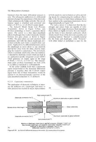
The Ashcroft Model XLdp Low Pressure phragm and sensor body are capable of with-
Transmitter, shown in Figure 9.19(a), uses standing a wide range of process fluids including
Si-Glass technology to form a capacitive silicon those which are highly corrosive. It is also import-
sensor. The sensor is a thin micro-machined ant for them to have thermal coefficients which
silicon diaphragm that is electrostatically bonded closely match those of the electrode assembly and
between two glass plates, as shown in Figure screening material. “Inconel” is a suitable material
9.19(b). The glass plates are each sputtered with for the body and diaphragm, while “Fosterite”
aluminum, and with the silicon diaphragm pos- with either nickel or palladium is used for the
itioned centrally each forms a parallel plate cap-
acitor. Application of a differential pressure causes
the diaphragm to move closer to one electrode
and further away from the other, thereby chan-
ging the respective capacitances. The movement,
which is extremely small (only a few micrometers),
is detected by electronic circuits which are built in
an application-specific integrated circuit (ASIC)
which generates an output signal in the range
420mA, 1-5V d.c. or 14V d.c. The measure-
ment spans of these transmitters are from 25Pa
to 12.5 kPa (2.5mmHzO to 1250mmHzO).
In the rather unlikely event that a pneumatic
signal proportional to the measured differential i
pressure is required, then the 4-20 mA output
signal from one of these transmitters would be
applied to an electropneumatic converter of the
type described in Section 31.7.3 of Part 4.
Ir
9.2.3.5 Capacitance manorneters
The application of electronic techniques to meas-
ure the deflection of a diaphragm and hence to
infer pressure has resulted in major improvements
High pressure port P2
Electrode connection for c2 I ,Aluminum electrode on glass substrate
\
’ I ‘Aluminum electrode on glass substrate
Electrode connection for Cl
Low pressure port PI
Maximum diaphragm travel due to applied pressurdetween 1 and 2 pm
Gap between diaphragm and capacitor electrodes-between 4 and 5 pm
Thickness of diaphragm-between 2 and 12 pm
(b) Differential capacitor formed by C1 and C2
Figure 9.19 (a) Ashcroft differential pressure transmitter; (b) construction of the sensor.