
Page 151 - Instrumentation Reference Book 3E
P. 151
Pressure measurement 135
The mechanical strength of silicon depends
largely on the state of the surface and in genera1
this imposes an upper limit of about 100 MPa on
the pressures that can be measured safely by the
sensors. The lower limit is about 2OkPa and is
determined by the minimum thickness to which
the diaphragm can be manufactured reliably.
Both the gauge factor G and resistance R of the
diffused resistors are sensitive to changes of tem-
perature, and the sensors need to be associated
with some form of compensating circuits. In some
instances this is provided by discrete resistors
closely associated with the gauge itself. Others
Figure 9.26 Schematic drawing of pressure sensing utilize hybrid circuits, part of which may be on
element. Courtesy, Kistler Instruments Ltd. the chip itself. Individual compensation is always
required for the zero offset, the measurement
span, and temperature stabilization of the zero.
of n-type silicon, each pair having one resistor Further improvement in the performance can be
with its principal component radial and one achieved by compensating for the nonlinearity
with its principal component circumferential. As and the effect of temperature on the span.
described later, this provides means for compen-
saiing the temperature-sensitivity of the silicon.
Mechanically they form part of the diaphragm 9.2.4.2 Strain gauge pressarre semm
but they are isolated electrically by the p-n junc- Another group of pressure sensors is based on
tion so that they function as strain gauges. The strain-gauge technology (see Chapter 4), in which
diaphragm is formed by cutting a cylindrical the resistance-type strain senscrs are connected in
recess on the rear surface of the wafer using ini- a Wheatstone bridge network. To achieve the
tially ultrasonic or high-speed diamond machining required long-term stability and freedom from
and finally chemical etching. This unit is then hysteresis, the strain sensors must have a molecu-
bonded to a similar unprocessed chip so that a lar bond to the deflecting inember which in addi-
hcmogeneous element is produced. If it is desired tion must also provide the necessary electrical
to measure absolute pressures the bonding is isolation over the operating temperature range
effected mder a vacuum. Otherwise the cavity of the transducer.
behind the diaphragm is connected via a hole in This can be achieved by first sputtering the
the base chip and a bonded tube to the atmos- electrical isolation layer on the stainless-steel sen-
pheric or reference pressure. The schematic sor beam or diaphragm and then sputtering the
arrangements of two such transducers are shown thin-film strain-gauge sensors on top of this. An
in Figure 9.27. example of this type of sensor is the TransInstru-
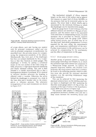
ments 4000 series shown in Figure 9.28.
The pressure inlet adaptor is fabricated from
precipitation-hardened stainless steel and has a
deep recess between the mounting thread and
electrod& deposited on
7 underside)
-Sreel membrane r Isolator mass
Figure 9.27 Cross-section of piezo-resistive pressure
transducer. (a) For absolute pressure. (b) For gauge Figure 9.28 Pressure transducer utilizing strain gauge
pressure. Courtesy, Kistler Instruments Ltd. sensor. Courtesy,Translnstrumen?s.