
Page 155 - Instrumentation Reference Book 3E
P. 155
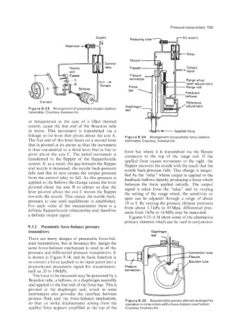
Pressure transmitters 139


                                              Conti ’0 I
                                           I=-
                                              relay

                                            output


                  Element
             Figure 9.33  Arrangement of pneumatic motion-balance
             transmitter. Courtesy, lnvensys Inc.
             or  temperature  in  the  case  of  a  filled  thermal
             system, cause the  free end  of  the  Bourdon  tube
             to  move.  This  movement  is  transmitted  via  a   &-        Applied force
             linkage to the lever that pivots about the axis A.   Figure 9.34  Arrangement of  pneumatic force-balance
             The free end of this lever bears on a second lever   transmitter. Courtesy, lnvensys Inc.
             that is pivoted at its center so that the movement
             is thus transmitted to a third lever that is free to   force bar  where it is  transmitted  via  the  flexure
             pivot  about the  axis C. The initial movement  is   connector  to  the  top  of  the  range  rod.  If  the
                       to  the  flapper  Of  the  flapper/nozz1e   applied force causes movement to the  right,  the
             system. If; as a resu1t; the gap between the flapper   flapper uncovers the nozzle with the result that the
             and nozzle is increased, the nozzle back-pressure   nozzle back-pressure falls. This &ange  is magni-
             falls and this in turn causes the output pressure   fied by the “relay,, whose output is appiied to the
             from the          to    As this pressure is   feedback bellows thereby producing a force which
             applied to the bellows the change causes the lever   balances  the  force  applied  initially,  The  output
             pivoted  about  the  axis B to  retract  so that  the   signal is taken  from the  “relay9, and  by  varying
             lever pivoted about the axis   the flapper   the  setting of the  range  wheel, the  sensitivity or
             towards the nozzle. This causes the nozzle back-   span can  be  adjusted  through  a  range  of  about
             pressure  to  rise  until  equilibrium  is  established.   to   By varying the primary element pressures
             For  each    Of  the measurement  there  is  a   from about  1.3kPa to  85Mpa, differential pres-
             definite flapperhozzle relationship  and therefore   sures from  kpa to 14 MPa may be measured,
             a definite output signal.                  Figures 9.35-9.38  show some of the alternative
                                                      primary elements which can be used in conjunction
             9.3.2  Pneumatic force-balance pressure
             transmitters
             There  are many  designs of pneumatic  force-bal-
             ance transmitters, but in Invensys Inc. design the
             same force-balance mechanism is used in all the
             pressure and differential pressure transmitters. It                  Connection tube
             is shown in Figure 9.34, and its basic function is                   Flexure
             to convert a force applied to its input point into a                 Bourdon tube
             proportional pneumatic  signal for transmission,   Pr
             such as 20 to 100 kPa.
               The force to be measured may be generated by a
             Bourdon tube, a bellows, or a diaphragm assembly
             and applied to the free end of the force bar. This is
             pivoted  at  the  diaphragm  seal;  which  in  some
             instruments  also  provides  the  interface  between
             process fluid  and  the  force-ba1ance mechanism,   Figure 9.35 Bourdon tube primaryelement arranged  for
             SO  that  Bn  initial  displacement arising from  the   operation in conjunction with a force-balance mechanism,
             applied force appears amplified at the top of  the   Courtesy, Invensys Inc.