
Page 158 - Instrumentation Reference Book 3E
P. 158
142 Measurement of pressure
As (il - ir) and (il + i? - ic) are proportional to
the input signals of amplifier U1 and U, it follows
that the output from the dividing stage is propor-
tional to the applied differential pressure.
Most differential pressure transmitters are used
in conjunction with orifice plates to measure
flow. If, therefore, the output from the dividing
stage is applied to a square root extracting circuit
then its output becomes proportional to flow
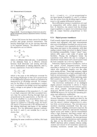
Figure 9.45 Functional diagram of electronic circuit for rate.
gauge and absolute pressure capacitance sensor. Courtesy,
Siemens Ltd.
9.3.4 Digital pressure transducers
Figure 9.45 shows the basic circuit for absolute Until recently digital data acquisition and control
pressure and gauge pressure transmitters. The systems were designed with their measurement
sensing diaphragm acts as the moving electrode and control intelligence localized in a central com-
in the capacitor detector. The effective values of puter. Transducers were required to do little more
the capacitors are as follows: than sense and report to the computer, with their
A&
c1 =--cs analog outputs being converted to digital format
do for interface compatibility. Today’s “smart” trans-
A& mitters offer users a new order of power and
cz =- flexibility. Placing the intelligence within the
do + Ad + cs transmitter easily allows the user to configure a
where A is effective electrode area, E is permittivity distributed measurement and control system from
of the dielectric fluid, do is effective distance the host computer via a two-way digital bus.
between fixed electrodes and sensing electrode. Inherently digital pressure transducers. such as
Ad is displacement of sensing electrode, and Cs the quartz crystal frequency-output sensors
is stray capacitance. From this it follows that described in Section 9.2.4.3, have been developed
which offer significant benefits over the older
style analog devices. These high accuracy digital
pressure transducers have been combined with a
which is the same as the deflection constant for built-in microprocessor capability to yield intelli-
the sensing diaphragm so that Ad is proportional gent pressure transmitters. While operating under
to the differential pressure which can therefore be field conditions, these transmitters can offer per-
measured by an all-bridge network. To compen- formance comparable to the primary standards.
sate for the effect of stray capacitances a capaci- The electronics architecture of an intelligent
tor C is included in the bridge circuit but supplied digital pressure transmitter is shown in Figure
with a voltage in anti-phase to that applied to Cl 9.46. The digital interface board contains a preci-
and Cr. sion clock, counter. microprocessor, RS-232
If the impedances of the capacitors C1, C2. and serial port, RS-485 serial port, and EPROM and
C3 are high compared with their associated resis- EEPROM memory for storing the operating pro-
tors then the currents flowing through them are gram and calibration coefficients.
proportional to the capacitances, so that the out- The digital interface board uses the two con-
put from amplifier U1 is proportional to (il - il) tinuous frequency output signals provided by the
and from amplifier Uz(i2 - ic). When these two pressure transducer (corresponding to pressure
signals are applied to a dividing stage, the result- and the sensor’s internal temperature) to calcu-
ant signal is proportional to the displacement of late fully corrected pressure. The microprocessor
the sensing electrode and hence to the applied monitors incoming commands from the com-
pressure. For the differential pressure transmit- puter. When a sampling command is received, the
ter, both Cl and Cz are variable but it can be microprocessor selects the appropriate frequency
shown that signal source and makes a period measurement
Ad CI - c, using a high frequency time-base counter and a
-
- user-specified integration time. When the period
-
do CI + c2 -2cs measurements are completed, the microprocessor
Applying the same conditions as before, this leads makes the appropriate calculations and transmits
to the data on the RS-232/485 bus. The RS-232/
RS485 interfaces allow complete remote config-
uration and control of all transmitter operations,
including resolution, sample rate, integration