
Page 154 - Instrumentation Reference Book 3E
P. 154
138 Measurement of pressure
fork temperature
sensor
Input pressure
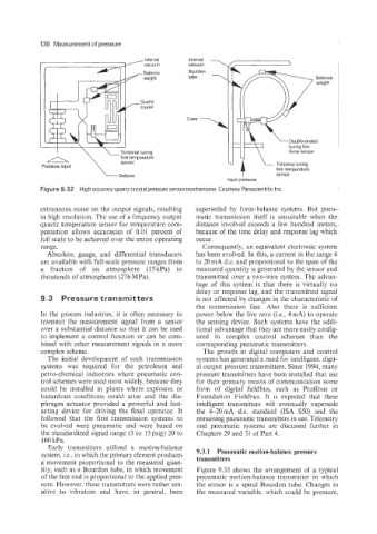
Figure 9.32 High accuracy quartz crystal pressure sensor mechanisms. Courtesy Paroscientific Inc
extraneous noise on the output signals, resulting superseded by force-balance systems. But pneu-
in high resolution. The use of a frequency output matic transmission itself is unsuitable when the
quartz temperature sensor for temperature com- distance involved exceeds a few hundred meters,
pensation allows accuracies of 0.01 percent of because of the time delay and response lag which
full scale to be achieved over the entire operating occur.
range. Consequently, an equivalent electronic system
Absolute, gauge, and differential transducers has been evolved. In this, a current in the range 4
are available with full-scale pressure ranges from to 20 mA d.c. and proportional to the span of the
a fraction of an atmosphere (15kPa) to measured quantity is generated by the sensor and
thousands of atmospheres (276 MPa). transmitted over a two-wire system. The advan-
tage of this system is that there is virtually no
delay or response lag, and the transmitted signal
9.3 Pressure transmitters is not affected by changes in the characteristic of
the transmission line. Also there is sufficient
In the process industries, it is often necessary to power below the live zero (Le., 4mA) to operate
transmit the measurement signal from a sensor the sensing device. Such systems have the addi-
over a substantial distance so that it can be used tional advantage that they are more easily config-
to implement a control function or can be com- ured in complex control schemes than the
bined with other measurement signals in a more corresponding pneumatic transmitters.
complex scheme. The growth in digital computers and control
The initial development of such transmission systems has generated a need for intelligent, digit-
systems was required for the petroleum and al output pressure transmitters. Since 1994, many
petro-chemical industries where pneumatic con- pressure transmitters have been installed that use
trol schemes were used most widely, because they for their primary means of communication some
could be installed in plants where explosive or form of digital fieldbus, such as Profibus or
hazardous conditions could arise and the dia- Foundation Fieldbus. It is expected that these
phragm actuator provided a powerful and fast- intelligent transmitters will eventually supersede
acting device for driving the final operator. It the 4-2OmA d.c. standard (ISA S50) and the
followed that the first transmission systems to remaining pneumatic transmitters in use. Telemetry
be evolved were pneumatic and were based on and pneumatic systems are discussed further in
the standardized signal range (3 to 15psig) 20 to Chapters 29 and 31 of Part 4.
100 kPa.
Early transmitters utilized a motion-balance
system, i.e., in which the primary element produces 9.3.1 Pneumatic motion-balance pressure
transmitters
a movement proportional to the measured quan-
tity, such as a Bourdon tube, in which movement Figure 9.33 shows the arrangement of a typical
of the free end is proportional to the applied pres- pneumatic motion-balance transmitter in which
sure. However, these transmitters were rather sen- the sensor is a spiral Bourdon tube. Changes in
sitive to vibration and have, in general, been the measured variable, which could be pressure,