
Page 149 - Instrumentation Reference Book 3E
P. 149
Pressure measurement 133
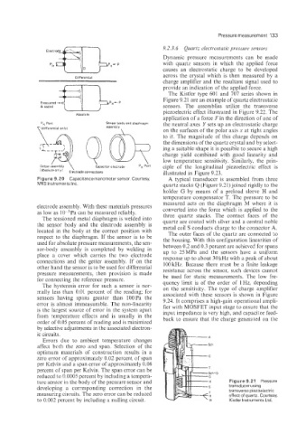
9.2.3.6 Quartz electrostatic pressure sensors
Dynamic pressure measurements can be made
with quartz sensors in which the applied force
causes an electrostatic charge to be developed
across the crystal which is then measured by a
Differential
charge amplifier and the resultant signal used to
provide an indication of the applied force.
The Kistler type 601 and 707 series shown in
Figure 9.21 are an example of quartz electrostatic
sensors. The assemblies utilize the transverse
piezoelectric effect illustrated in Figure 9.22. The
Absolute
application of a force Fin the direction of one of
PR Port Sensor body and diaphragm the neutral axes Y sets up an electrostatic charge
yldifferential only) assembly
\ on the surfaces of the polar axis x at right angles
to it. The magnitude of this charge depends on
the dimensions of the quartz crystal and by select-
ing a suitable shape it is possible to secure a high
charge yield combined with good linearity and
low temperature sensitivity. Similarly, the prin-
ciple of the longitudinal piezoelectric effect is
iabsolute Only' Elictrode connections illustrated in Figure 9.23.
Figure 9.20 Capacitance manometer sensor. Courtesy, A typical transducer is assembled from three
MKS Instruments Inc. quartz stacks Q (Figure 9.21) joined rigidly to the
holder G by means of a preload sleeve H and
temperature compensator T. The pressure to be
measured acts on the diaphragm M where it is
electrode assembly. With these materials pressures converted into the force which is applied to the
as low as 10-3Pa can be measured reliably. three quartz stacks. The contact faces of the
The tensioned metal diaphragm is welded into
the sensor body and the electrode assembly is quartz are coated with silver and a central noble
metal coil S conducts charge to the connector A.
located in the body at the correct position with The outer faces of the quartz are connected to
respect to the diaphragm. If the sensor is to be the housing. With this confignration linearities of
used for absolute pressure measurements, the sen- between 0.2 and 0.3 percent are achieved for spans
sor-body assembly is completed by welding in up to 25MPa and the sensors have a uniforn;
place a cover which carries the two electrode
connections and the getter assembly. If on the response up to about 30 lcHz with a peak of about
100 kHz. Because there Eust be a finite leakage
other hand the sensor is to be used for differential
pressure measurements, then provision is made resistance across the sensor, such devices cannot
for connecting the reference pressure. be used for static measurements. The low fre-
quency limit is of the order of 1 Hz. depending
The hysteresis error for such a sensor is nor-
mally less than 0.01 percent of the reading: for on the sensitivity. The type of charge amplifier
associated with these sensors is shown in Figure
sensors having spans greater than l0OPa the
error is almost immeasurable. The non-linearity 9.24. It comprises a high-gain operational ampli-
fier with MOSFET input stage to ensure that the
is the largest source of error in the system apart input impedance is very high, and capacitor feed-
from temperature effects and is usually in the back to ensure that the charge generated 011 the
order of 0.05 percent of reading and is minimized
by selective adjustments in the associated electron-
ic circuits.
Errors due io ambient temperature changes
affect both the zero and span. Selection of the
optimum materials of construction results in a
zero error of approximately 0.02. percent of span
per Kelvin and a span error of approximately 0.06
percent of span per Kelvin. The span error can be
reduced to 0.0005 percent by including a tempera- SchiD
0
ture sensor in the body of the pressure sensor and H Figure 9.21 Pressure
developing a corresponding correction in the transducer using
transverse piezoelectric
measuricg circuits. The zero error can be reduced effect of quartz. Courtesy,
to 0.002 percent by including a nulling circuit. Kistler Instruments Ltd.