
Page 146 - Instrumentation Reference Book 3E
P. 146
130 Measurement of pressure
High pressure diaphragm
(Do not remove)
Range spring nut
pressure diaphragm
Figure 9.14 Diaphragm type differential pressure transmitter Courtesy, lnvensys Inc
High pressure 1 Low pressure
I
Aluminum can
I \
Beliows
20-100 kPa lacting in
input compression)
U
1 Pivot
Damping =w+7,?,
adjustment
needle
valve
5 ’ k4
pointer
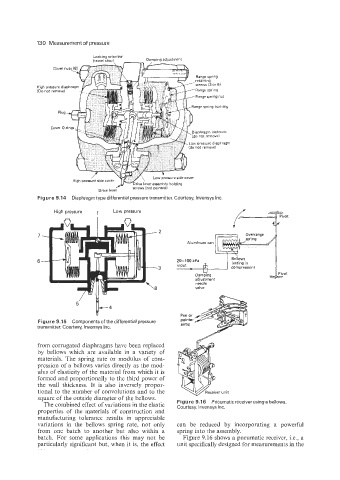
Figure 9.15 Components of the differential pressure Pen or
arms
transmitter. Courtesy, lnvensys Inc.
from corrugated diaphragms have been replaced
by bellows which are available in a variety of
materials. The spring rate or modulus of com-
pression of a bellows varies directly as the mod-
ulus of elasticity of the material from which it is
formed and proportionally to the third power of
the wall thickness. It is also inversely propor-
tional to the number of convolutions and to the er unit
square of the outside diameter of the bellows.
The combined effect of variations in the elastic Figure 9.1 6 Pneumatic receiver using a bellows.
Courtesy, lnvensys Inc.
properties of the materials of construction and
manufacturing tolerance results in appreciable
variations in the bellows spring rate, not only can be reduced by incorporating a powerful
from one batch to another but also within a spring into the assembly.
batch. For some applications this may not be Figure 9.16 shows a pneumatic receiver, Le., a
particularly significant but, when it is, the effect unit specifically designed for measurements in the