
Page 147 - Instrumentation Reference Book 3E
P. 147
Pressure measurement 131
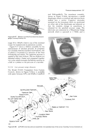
and 2000 mmH20). The transducer assembly,
shown in Figure 9.18(b), incorporates a metal
diaphragm which is stretched and electron-beam
welded into a carrier. Capacitor electrodes
mounted on the transducer shells are positioned
on either side of the diaphragm and adjusted so
that the requisite change in capacitance is
obtained for the specified pressure range. The
electrodes are connected in a Wheatstone bridge
network which is operated at 1.7MHz and is
*’
Figure 9.17 Bellows assembly for an absolute pressure
gauge. Courtesy lnvensys Inc.
range 20 to 100 kPa which is one of the standard
ranges for transmission in pneumatic systems.
Figure 9.17 shows a bellows assembly for the
measurement of absolute pressure. It comprises
two carefully matched stainless-steel bellows, one
of which is evacuated to a pressure of less than
0.05 mmHg and sealed. The unknown pressure is
applied to the other bellows. The two bellows are
mounted within a frame and connected together
via a yoke which transmits the bellows motion via
a link to a pointer or the pen arm of a recorder.
9.2.3.4 Low pressure range elements
The Model FC052 Transmitter from Furness
Controls, shown in Figure 9.18(a), is available
with spans between lOPa and 20kPa (1 mmH2O
p Diaphragm Assy
(b)
Figure 9.1 8 (a) FC052 ultra-low-pressure transmitter, (b) exploded view of the sensor Courtesy, Furness Controls Ltd