
Page 145 - Instrumentation Reference Book 3E
P. 145
Pressure measurement 129
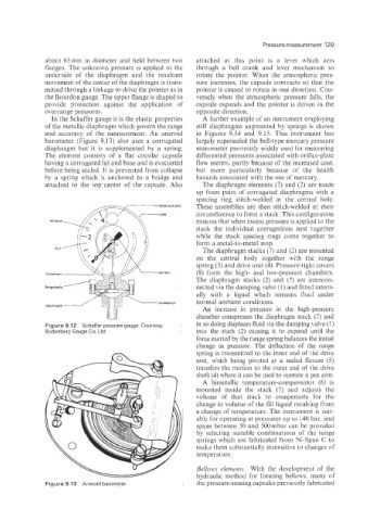
about 65 mm in diameter and held between two attached at this point is a lever which acts
Ranges. The unknown pressure is applied to the through a bell crank and Lever mechanism to
underside of the diaphragm and the resultant rotate the pointer. When the atmospheric pres-
movement of the center of the diaphragm is trans- sure increases, the capsule contracts so that the
mitted through a linkage to drive the pointer as in pointer is caused to rotate in one direction. Con-
the Bourdon gauge. The upper flange is shaped to versely when the atmospheric pressure falls, the
provide protection against the application of capsule expands and the pointer is driven in the
overrange pressures. opposite direction.
In the Schaffer gauge it is the elastic properties A further example of an instrument employing
of the metallic diaphragm which govern the range stiff diaphragms augmented by springs is shown
and accuracy of the measurement. An aneroid in Figures 9.14 and 9.15. This instrument has
barometer (Figure 9.13) also uses a corrugated largely superseded the bell-type mercury pressure
diaphragm but it is supplemented by a spring. manometer previously widely used for measuring
The element consists of a flat circular capsule differential pressures associated with orifice-plate
having a corrugated lid and base and is evacuated flow meters: partly because of the increased cost,
before being sealed. It is prevented from collapse but more particularly because of the health
by a spring which is anchored to a bridge and hazards associated with the use of mercury.
attached to the top center of the capsule. Also The diaphragm elements (7) and (2) are made
up from pairs of corrugated diaphragms with a
spacing ring stitch-welded at the central hole.
window 6 These assemblies are then stitch-welded at their
circumference to form a stack. This configuration
x, ensures that when excess pressure is applied to the
stack the individual corrugations nest together
while the stack spacing rings come together to
form a metal-to-metal stop.
The diaphragm stacks (7) and (2) are mounted
on the central body together with the range
spring (3) and drive unit (4). Pressure-tight covers
(8) form the high- and low-pressure chambers.
The diaphragm stacks (2) and (7) are intercon-
nected via the damping valve (1) and fitted intern-
ally with a liquid which remains fluid under
normal ambient conditions.
An increase in pressure in the high-pressure
chamber compresses the diaphragm stack (7) and
Figure 9.12 Schaffer pressure gauge. Courtesy, in so doing displaces fluid via the damping valve (I)
Budenberg Gauge Co. Ltd. into the stack (2) causing it to expand until the
force exerted by the range spring balances the initial
change in pressure. The deflection of the range
spring is transmitted to the inner end of the drive
unit, which being pivoted at a sealed flexure (5)
transfers the motion to the outer end of the drive
shaft (4) where it can be used to operate a pen arm.
A bimetallic temperature-compensator (6) is
mounted inside the stack (7) and adjusts the
volume of that stack to compensate for the
change in volume of the fill liquid resulting from
a change of temperature. The instrument is suit-
able for operating at pressures up to 140 bar, and
spans between 50 and 500mbar can be provided
by selecting suitable combinations of the range
springs which are fabricated from Ni-Span C to
make them substantially insensitive to changes of
temperature.
Bellows elements With the development of the
hydraulic method for forming bellows, many of
Figure 9.13 Aneroid barometer the pressure-sensing capsules previously fabricated