
Page 156 - Instrumentation Reference Book 3E
P. 156
140 Measurement of pressure
Non-wetted Wetted side with this force-balance mechanism to measure
w Bei‘owr gauge, differential, and absolute (high and low)
side
pressures.
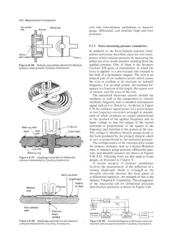
9.3.3 Force-measuring pressure transmitters
In addition to the force-balance pressure trans-
mitters previously described, there are now trans-
mitters which measure pressure by measuring the
deflection of an elastic member resulting from the
Figure 9.36 Bellows type primaryelement forabsolute applied pressure. One of these is the Invensys
pressure measurements. Courtesy, lnvensys Inc. Foxboro 820 series of transmitters, in which the
force is applied to a pre-stressed wire located in
the field of a permanent magnet. The wire is an
integral part of an oscillator circuit which causes
the wire to oscillate at its resonant (or natural)
frequency. For an ideal system, the resonant fre-
quency is a function of the length, the square root
of tension. and the mass of the wire.
The associated electronic circuits include the
oscillator as well as the components to convert
oscillator frequency into a standard transmission
signal such as 4 to 20 mA d.c. As shown in Figure
9.39 the oscillator signal passes via a pulse-shaper
-- to two frequency converters arranged in cascade,
each of which produces an output proportional
Weld \ High uk input voltage so that the output of the second
to the product of the applied frequency and its
Back-up plate C-flexure converter is proportional to the square of the
frequency and therefore to the tension in the wire.
,Diaphragm
The voltage is therefore directly proportional to
the force produced by the primary element which
in turn is proportional to the measured pressure.
The configurations of the resonant-wire system
for primary elements such as a helical Bourdon
tube, to measure gauge pressure, differential pres-
\ Low
Welding ring sure, and absolute pressure are shown in Figures
Figure 9.37 Diaphragm assembly for differential 9.40-9.43. Vibrating wires are also used as strain
pressure measurements. Courtesy lnvensys Inc. gauges, as discussed in Chapter 4.
A second category of pressure transmitters
involves the measurement of the deflection of a
sensing diaphragm which is arranged as the
movable electrode between the fixed plates of
Back-up plate
a differential capacitor. An example of this is the
Diaphragm Siemens Teleperm K Transmitter. The arrangement
I Gasket of the measuring cell for differential pressures
and absolute pressures is shown in Figure 9.44.
Non-wetted
side
beam
welded
Figure 9.38 Diaphragm assembly for low absolute Figure 9.39 Functional diagram of electronic circuit for
pressure measurements. Courtesy, lnvensys Inc. resonant wire pressure transmitter. Courtesy, lnvensys Inc.