
Page 217 - Instrumentation Reference Book 3E
P. 217
Terminology 201
ent
Figure 13.3 Components of a microprocessor-based transmitter with a secondarysensor.
4-20 mA
measurement
Communication
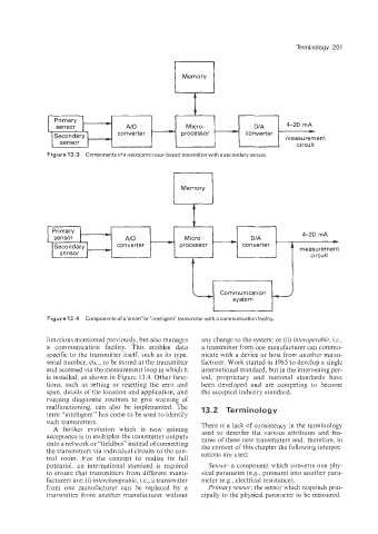
Figure 13.4 Components of a”smarl”or ”intelligent” transmitter with a communication facility.
Functions mentioned previously, but also manages any change to the system; or (ii) intevoyemble, i.e.,
a communication facility. This enables data a transmitter from one manufacturer can commu-
specific to the transmitter itself, such as its type, nicate with a device or host from another manu-
serial number, etc., to be stored at the transmitter facturer. Work started in 1985 to develop a single
and accessed via the measurement Poop in which it international standard, but in the intervening per-
is installed, as shown in Figure 13.4. Other func- iod, proprietary and national standards have
tions, such as setting or resetting the zero and been developed and are competing to become
span. details of the location and application, and the accepted industry standard.
running diagnostic routines to give warning of
malfunctioning, can also be implemented. The 13.2 Terminology
term “intelligent” has come to be used to identify
such transmitters.
A further evolution which is now gaining There is a lack of consistency in the terminology
acceptance is to multiplex the transmitter outputs used to describe the various attributes and fea-
tures of these new transmitters and, therefore, in
onto a network or “fieldbus” instead of connecting the context of this chapter the following interpre-
the transmitters via individual circuits to the con- tations are used:
trol room. For the concept to realize its full
potentiaI, an international standard is required Sensor: a component which converts one phy-
to ensure that transmitters from different manu- sical parameter (e.g.. pressure) into another para-
facturers are: (i) interchlznrzgeable, i.e., a transmitter meter (e.g.. electrical resistance).
k-om one manufacturer can be replaced by a PY~MFJ, seizsuv: the sensor which responds prin-
transmitter from another manufacturer without cipally to the physical parameter to be measured.