
Page 213 - Instrumentation Reference Book 3E
P. 213
In-fiber sensing structures 197
where E is the applied longitudinal train on the (Figure 12.32(b)) resulting from the structural
fiber and pc is the effective photoelastic coeffi- changes induced in the fiber by the surrouiiding
cient having the form: hydrostatic pressure (Xu etal. 1993). In this case
the fiber is compressed under the action of the
pressure force and the fractional change in Bragg
wavelength is then given by:
where pll and p12 are the strain-optic tensor
coefficients, E/ is Poisson’s ratio, and IZ is the core
refractive index. Typically pe has a value of 0.22 where h is the spatial period of the grating, and n
related
the
and AXB~~.~~/XB~~~~ applied stress is the core refractive index. It has then been
to
is
by the relation AXB~~~~/XB~~~~ = 7.5 x 10⁻⁸/t. shown that this fractional change can be related
The measurement of strain is complicated by the to the mechanical properties of the fiber by:
effect of the thermal expansion of the body under
measurement, which produces an effect referred to
as the “apparent strain.” It is necessary to remove
the latter in the measurement to reveal the “true
strain” effect. This is conventionally done by pro- (12.59)
viding a second dummy sensor (Measures 1992) where E is Young’s modulus and the other sym-
which is placed in the vicinity of the strain monitor bols have the assignments given earlier. Measure-
but desensitized to the strain effect, thus only pro- ments of the fractional change when the grating
viding a measure of the temperature environment. structure was subjected to pressures of up to
It is then necessary to subtract the thermal “appar- 70Mpa showed a linear response, with a figure
ent strain” measured by the dummy sensor from of -1.98 x lop6 MPa. By contrast, the tempera-
the combined “real and apparent strain” measured ture effect gave a fractional change of
by the first strain sensor. +6.72 x 10-61”C (0.01045nml“C). Therefore, as
It is also possible to write Bragg gratings in with the measurement of strain, there is a need to
polarization maintaining optical fibers that have eliminate the effect of temperature on the pressure
two orthogonal polarization propagating modes reading in order to obtain a true pressure value.
(Morey et al. 1989; Measures et al. 1992). Since To measure the change in the central Bragg
each polarization eigenmode has a slightly differ- reflected wavelength it is convenient to use a con-
ent associated refractive index, the optical path ventional spectrometer or optical spectrim ana-
grating period will be different for the two axes; lyzer. These devices, however, have a limited
the Bragg wavelength differences between the two response time (up to the order of milliseconds)
modes are typically of the order of 0.1 nni. and are costly items. For a low-cost sensor appli-
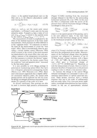
As already mentioned, fiber gratings can also cation, wavelength demodulation has been demon-
be used to monitor high pressure environments strated by the use of appropriately selected
Broad-Band In-Fiber Bragg
Source 3dB Fiber Coupler Grating Sensor
YllllllllllYtllRlll-
Fiber Link Back-Reflected
Wavelength hragg
Ratiometric Output
Signal
Amp.
Figure 12.32 Radiometric wavelength dependent detection system for demodulating the reflected Bragg wavelength
(Measures et ai. 1992).