
Page 211 - Instrumentation Reference Book 3E
P. 211
in-fiber sensing structures 195
where y11 and ylz are the strain-optic coefficients It can be seen that by varying the angle of inter-
and v is Poisson‘s ratio. section of the two interfering beams, the period of
Hn general, the cosine form of the fringe output the grating, and thus the wavelength at which the
means tha.t the phase change will be multifunc- grating structure will reflect incident radiation
tional, and ambiguities can arise when the phase propagating along the optical fiber can be altered.
~
~
~
is greater than 2n. As discussed earlier, dual- The wavelength X B at which a grating period A
~
wavelength interrogation can be used to remove back-reflects is given by:
such processing uncertainties.
XBragg = 2ncA (12.53)
12.5.3 Fiber Bragg grating sensing element The efficiency R of the grating structure in reflect-
ing back a particular wavelength AB^^^^ is deter-
A second example of an in-fiber sensing structure mined by: the length L of the grating structure,
is the holographic fiber Bragg grating. This device and hence the number of grating elements; the
is essentially a linear grating structure that is reflectivity of each element, Le.. the refractive
formed in the core of an optical fiber through index depth of variation (Aiiln,) produced by
the periodic modulation of its refractive index the writing process; and the fraction of the inte-
along a fixed length of the fiber (Figure 12.29). grated mode intensity that is concentrated in the
The periodic modulation of the core refractive fiber core q(V), ~(v) N 1 - l/V2 where the nor-
index is produced by (he interaction of UV laser malized fiber frequency, V > 2.4. The expression
radiation with defect structures in some doped given by Morey et al. (1989) is:
silica optical fibers through a photorefractive
ABragg ]
process (see Morep etal. 1989). The absorption 1 nLAn?$C’)
of radiation about the 245 nm wavelength, for R=tanh-[ (12.54)
example, is associated with the germanium-
oxygen vacancy defect band structure. Grating The rate at which a Bragg grating can be written
structures are usually written in the core of silica in the fiber core depends on the radiation power
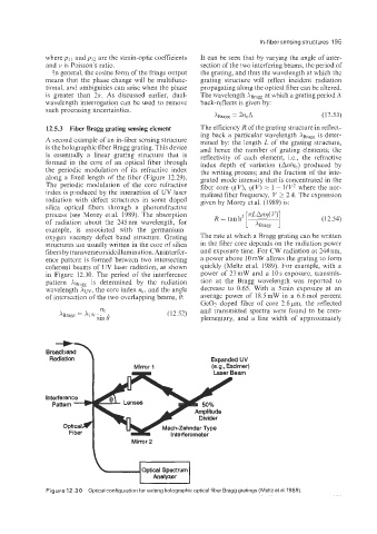
fibersbytransverseorsideillumination. Aninterfer- and exposure time. For CW radiation at 244nm,
ence pattern is formed between two intersecting a power above lOmW allows the grating to form
coherent beams of UV laser radiation, as shown quickly (Meltz et al. 1989). For example, with a
in Figure 12.30. The period of the interference power of 23mW and a 10s exposure, transmis-
~
pattern X B is ~determined ~by the radiation sion at the Bragg wavelength was reported to
~
wavelength XUV, the core index n,, and the angle decrease to 0.65. With a 5miii exposure at an
of intersection of the two overlapping beams, 0: average power of l8.5mW in a 6.611101 percent
GeO? doped fiber of core 2.6pm, the reflected
(12.52) and transmitted spectra were found to be com-
plementary, and a line width of approximately
Broad band
Radiation Expanded UV
Mirror 1 (e.g., Excimer)
Laser Beam
Optical Spectrum
Analyzer
I
Figure 12.30 Optical configuration for writing holographic optical fiber Bragg gratings (Meltz et al. 1989).