
Page 208 - Instrumentation Reference Book 3E
P. 208
192 Fiber optics in sensor instrumentation
-+ Processing Electronics: Signal
Phase Tracker Analyzer
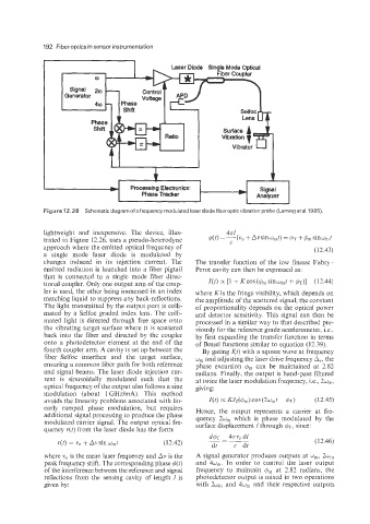
Figure 12.26 Schematic diagram of a frequencymodulated laserdiodefiberopticvibration probe (Lamingeta1.1985).
lightweight and inexpensive. The device, illus-
trated in Figure 12.26, uses a pseudo-heterodyne
approach where the emitted optical frequency of (12.43 j
a single mode laser diode is modulated by
changes induced in its injection current. The The transfer function of the low finesse Fabry-
emitted radiation is launched into a fiber pigtail Perot cavity can then be expressed as:
that is connected to a single mode fiber direc-
tional coupler. Only one output arm of the coup- I(t) oc[1 +Kcos($,sinw,t+$Tj] (12.44)
ler is used, the other being immersed in an index where K is the fringe visibility, which depends on
matching liquid to suppress any back-reflections. the amplitude of the scattered signal; the constant
The light transmitted by the output port is colli- of proportionality depends on the optical power
mated by a Selfoc graded index lens. The colli- and detector sensitivity. This signal can then be
mated light is directed through free space onto processed in a similar way to that described pre-
the vibrating target surface where it is scattered viously for the reference grade accelerometer, i.e.,
back into the fiber and directed by the coupler by first expanding the transfer function in terms
onto a photodetector element at the end of the of Bessel functions similar to equation (12.39).
fourth coupler arm. A cavity is set up between the By gating I(t) with a square wave at frequency
fiber-Selfoc interface and the target surface, w, and adjusting the laser drive frequency A,, the
ensuring a common fiber path for both reference phase excursion $, can be maintained at 2.82
and signal beams. The laser diode injection cur- radians. Finally, the output is band-pass filtered
rent is sinusoidally modulated such that the at twice the laser modulation frequency, i.e., 2w,,
optical frequency of the output also follows a sine giving:
modulation (about 1 GHz/mA). This method
avoids the linearity problems associated with lin- I(t) cx KJz(&) COS (2wmt - d~) (12.45)
early ramped phase modulation, but requires Hence, the output represents a carrier at fre-
additional signal processing to produce the phase quency 2w, which is phase modulated by the
modulated carrier signal. The output optical fre- surface displacement 1 through 4~, since:
quency ~(t) from the laser diode has the form:
v(t) = vo + Avsinw,t (12.42) (12.46)
where vo is the mean laser frequency and Av is the A signal generator produces outputs at w,, 2w,
peak frequency shift. The corresponding phase $(t) and 4w,. In order to control the laser output
of the interference between the reference and signal frequency to maintain 6, at 2.82 radians, the
reflections from the sensing cavity of length I is photodetector output is mixed in two operations
given by: with 2w, and 4w, and their respective outputs