
Page 206 - Instrumentation Reference Book 3E
P. 206
190 Fiber optics in sensor instrumentation
As an example, for a target surface moving in a a maximum modulation depth of 20 percent as
periodic sinusoidal motion such that: described (<1 MHz).
4TA .
Qs(t) = ~ sin(2rf,t) (12.33)
A0 12.4.4.2 Pseudo-heterodyne modiilation-vibra-
the resulting dynamic component of the output tiorz monitoring
signal is given by: A different form of optical fiber vibration moni-
tor has been described (Meggitt etal. 1989) for
use as a non-contacting reference grade vibration
sensor. It was initially designed for use in cali-
brating secondary grade accelerometers, such as
[sin (2& + QO>l piezoelectric accelerometers, but has a general
applicability. The advantage in using an optical
The output spectrum is composed of a carrier approach for a reference grade device is that the
centered at frequency fB with sidebands at fre- system is capable of making displacement meas-
quency differences of f~ +fs. fB zt Zfs, fB 4 3f, urements which are referred only to the wave-
and so on. It is possible to select the first term length of the radiation used, in this case a HeNe
fB +fs by use of a band pass filter centered atfB gas laser at 623.8 nm. It can also be configured to
and with a bandwidth of less than +2fs(max). provide calibrations that are independent of the
The output frequency modulated signal can be temperature of the environment, allowing the
conveniently demodulated by use of a PLL temperature dependence of the piezoelectric
where the output error signal is proportional devices to be characterized.
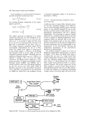
to the surface velocity v,. However, as the Bragg The vibration monitor is based on a form of
cell frequency shift is of the order of tens of Michelson optical fiber interferometer, as shown
megahertz (typically 40 MHz-100 MHz) and the in Figure 12.25. Here, the HeNe laser light is
maximum frequency shift&(,,,, is <1 MHz, it is launched into one port of a single mode fiber
difficult to design a PLL to cover this range. coupler. Radiation is directed via an output port
Therefore, the Bragg carrier frequency is first onto the vibrating surface being investigated,
down-converted by using conventional double- from which it is back-reflected into the optical
balanced mixers (DBM1 and DBM2) and a fiber coupler and transmitted back to a photo-
second oscillator offset from the Bragg frequency detector element. The second output port of the
by Af (i.e., at f~ + AJ). The mixer output is fiber coupler is wound several times around a
therefore centered on the intermediate frequency piezoelectrical cylinder that acts as a fiber stretch-
of Af, and this is conveniently set at a maximum er under the influence of a periodic modulating
of 5 MHz for which PLLs are available, having voltage. Some of the HeNe light will travel in this
Vibrating
Surface
I HeNeLaser I
Fiber Coupler
Photo
P2T modulator
VDU
output
Phase Tracker
Figure 12.25 Schematic of a referencegrade fiber opticvibration sensor (Meggitt et at. 1989).