
Page 204 - Instrumentation Reference Book 3E
P. 204
188 Fiber optics in sensor instrumentation
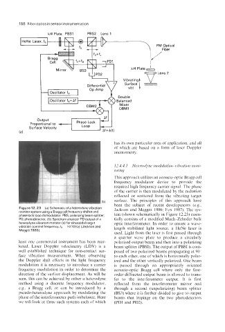
X/4 Plate PES1 PES2 Lens 1
has its own particular area of application, and all
of which are based on a form of laser Doppler
anemometry.
12.4.4. I tIetero&ne nio~lulatioii-vibrtIrioli moiii-
toring
This approach utilizes an acousto-optic Bragg cell
frequency modulator device to provide the
required high frequency carrier signal. The phase
of the carrier is then modulated by the radiation
reflected or scattered from the vibrating target
surface. The principles of this approach have
been the subject of recent developments (e.g.,
Figure 12.23 (a) Schematicofa heterodynevibration Jackson and Meggitt 1986: Fox 1987). The sys-
monitor system using a Bragg cell frequency shifter and
phase lock loop demodulator. PES, polarizing beam splitter; tem (shown schematically in Figure 12.23) essen-
PD, photodetector, (b) Spectrum analyzer PD output of a tially consists of a modified Mach-Zehnder bulk
heterodyne vibration monitor (a) for sinusoidal target optic interferometer. In order to ensure a wave-
vibration (central frequency,,fk - 80 MHz) (Jackson and length stabilized light source, a HeNe laser is
Meggitt 1986).
used. Light from the laser is first passed through
a quarter wave plate to produce a circularly
least one commercial instrument has been mar- polarized output beam and then into a polarizing
keted. Laser Doppler velocimetry (LDV) is a beam splitter (PBSI). The output of PBSI is com-
well established technique for non-contact sur- posed of two polarized beams propagating at 90"
face vibration measurement. When observing to each other, one of which is horizontally polar-
the Doppler shift effects in the light frequency ized and the other vertically polarized. One beam
modulation it is necessary to introduce a carrier is passed through an appropriately oriented
frequency modulation in order to determine the acousto-optic Bragg cell where only the first-
direction of the surface displacement. As will be order diffracted output beam is allowed to trans-
seen, this can be achieved by either a heterodyne fer to the interferometer output. It is first
method using a discrete frequency modulator, reflected from the interferometer mirror and
e.g., a Bragg cell, or can be introduced by a through a second (unpolarizing) beam splitter
pseudo-heterodyne approach by modulating the (BS3) where it is further divided to give to output
phase of the interferometer path imbalance. Here beams that impinge on the two photodetectors
we will look at three such systems each of which (PD1 and PD2).