
Page 209 - Instrumentation Reference Book 3E
P. 209
In-fiber sensing structures 193
are low bandpass filtered to give the &(a&) cos 4~ possible to produce many such short length sen-
and J4(&) cos &, and their ratio is used to con- sors into a given fiber length to form a quasi-
trol the AGC amplifier driving the laser diode. In distributed array of sensing elements. It is with
this way, any temperature effects in the laser this background that we now discuss in some
diode and variations in the sensing cavity are detail the sensing mechanisms and structures of
compensated for. A tracker is used that measures the in-fiber Fabry-Perot and the fiber Bragg
d+T/dt, which gives an output voltage propor- grating devices.
tional to surface velocity. The vibration sensor is
designed to operate with a sensor cavity of
50-300 mm. Vibration frequencies up to 20 kHz 12.5.2 Fiber Fabry-Perot sensing element
are measured; measurement is limited to the
region in which the frequency tracker gives good The fiber Fabry-Perot sensor (Kist etal. 1985;
linearity? with a maximum surface velocity up to Lee and Taylor, 1988) is a useful sensing device
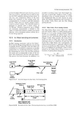
0.2 m/s being reported. because it is an in-line sensing element (Figure
12.27). It is essentially an optical cavity that is
defined by two semireflecting parallel mirrors
In-fiber sensing structures (Figure 12.28). More usually, the Fabry-Perot
cavity (at least in bulk optic form) has highly
12.5.1 Introduction reflecting mirrors of reflectivity R such that the
In-fiber sensing structures, such as the Fabry- device has a high finesse and, consequently, its
Perot and the Bragg grating elements, are proving refleetionltransmission is spectrally selective and
invaluable devices, especially when the fibers are serves as an interference filter element. The inten-
embedded in or attached to composite or metallic sity IT of radiation at wavelength X that is trans-
components for monitoring structural integrity. mitted by the Fabry-Perot device is given as a
By integrating the sensor into the fiber structure function of optical phase change by:
the sensor size is comparable to that of the ori-
ginal fiber dimensions and thus will only minim-
ally perturb the host structure. In addition, it is
Single Mode
Laser Diode Fiber Semi-Reflecting
Source Directional
Coupler
Sensing
Cavity
Fiber Lead Length L
Photo-
Detector
Figure 12.27 Schematic diagram of a fiber Fabry-Perot sensing system.
Reflective Fusion
Splice Mirrored Fiber
Single Mode
Fiber Core
-------
Length --d
Sensor Cavity
Fiber
Coating
Back Reflected Light
Phase Dflerence=@
Figure 12.28 Illustration ofafiber Fabry-Perotsensingstructure (e.g., Lee andTaylor1988).