
Page 313 - Instrumentation Reference Book 3E
P. 313
Temperature measurement considerations 297
Fractional heating Where the process fluid flows
past a probe at high velocity there is, especially in
the case of gases, a frictional heating effect. The
magnitude of the effect is not easily evaluated but
it is advisable if possible to site the probe at a
location where the fluid velocity is low.
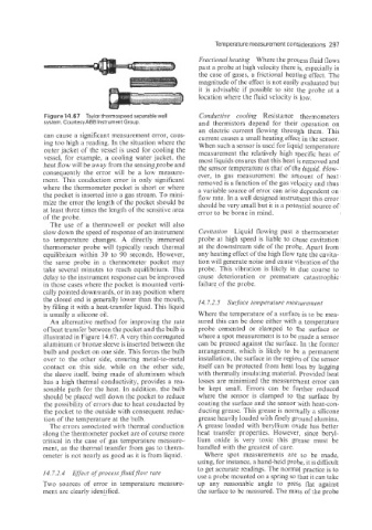
Figure 14.67 Taylor thermospeed separable well Coizdzictive cooling Resistance thermometers
system. CourtesyABB Instrument Group. and thermistors depend for their operation on
an electric current flowing through them. This
can cause a significant measurement error, caus- current causes a small heating effect in the sensor.
ing too high a reading. In the situation where the When such a sensor is used for liquid temperature
outer jacket of the vessel is used for cooling the measurement the relatively high specific heat of
vessel, for example, a cooling water jacket, the most liquids ensures that this heat is removed and
heat flow will be away from the sensing probe and the sensor temperature is that of the liquid. How-
consequently the error will be a low measure- ever, in gas measurement the amount of heat
ment. This conduction error is only significant removed is a function of the gas velocity and thus
where the thermometer pocket is short or where a variable source of error can arise dependent on
the pocket is inserted into a gas stream. To mini- flow rate. In a well designed instrument this error
mize the error the length of the pocket should be should be very small but it is a potential source of
at least three times the length of the sensitive area error to be borne in mind.
of the probe.
The use of a thermowell or pocket will also
slow down the speed of response of an instrument Cavitation Liquid flowing past a thermometer
to temperature changes. A directly immersed probe at high speed is liable to cause cavitation
thermometer probe will typically reach thermal at the downstream side of the probe. Apart from
equilibrium within 30 to 90 seconds. However, any heating effect of the high flow rate the cavita-
the same probe in a thermometer pocket may tion will generate noise and cause vibration of the
take several minutes to reach equilibrium. This probe. This vibration is likely in due course to
delay to the instrument response can be improved cause deterioration or premature catastrophic
in those cases where the pocket is mounted verti- failure of the probe.
cally pointed downwards, or in any position where
the closed end is generally lower than the mouth, 14.7.2.5 Swface temperatwe nieasurement
by filling it with a heat-transfer liquid. This liquid
is usually a silicone oil. Where the temperature of a surface is to be mea-
An alternative method for improving the rate sured this can be done either m7ith a temperature
of heat transf'er between the pocket and the bulb is probe cemented or clamped to the surface or
illuskated in Figure 14.67. A very thin corrugated where a spot measurement is to be made a sensor
aluminum or bronze sleeve is inserted between the can be pressed against the surface. In the former
bulb and pocket on one side. This forces the bulb arrangement, which is likely to be a permanent
over to the other side, ensuring metal-to-metal installation, the surface in the region of the sensor
contact on this side- while on the other side, itself can be protected from heat loss by lagging
the sleeve itself, being made of aluminum which with thermally insulating material. Provided heat
has a high theimal conductivity, provides a sea- losses are minimized the measurement error can
sonable path for the heat. In addition, the bulb be kept small. Errors can be further reduced
should be placed well down the pocket to reduce where the sensor is clamped to the surface by
the possibility of errors due to heat conducted by coating the surface and the sensor with heat-con-
the pocket to the outside with consequent reduc- ducting grease. This grease is normally a silicone
tion of the temperature at the bulb. grease heavily loaded with finely ground alumina.
The errors associeted with thermal conduction A grease loaded with beryllium oxide has better
along the thermometer pocket are of course more heat transfer properties. However, since beryl-
critical in the case of gas temperature measure- lium oxide is very toxic this grease must be
ment, as the thermal transfer from gas to therm- handled with the greatest of care.
ometer is not nearly as good as it is from liquid. Where spot measurements are to be made;
using, for instance, a hand-heid probe. it is dificult
to get accurate readings. The normal practice is to
14.7.2.4 Effect of process fluidflow rate use a probe mounted on a spring so that it can take
Two sources of error in temperature measure- up any reasonable angle to press flat against
ment are clearly identified. the surface to be measured. The mass of the probe