
Page 311 - Instrumentation Reference Book 3E
P. 311
Temperature measurement considerations 295
?
t t
Figure 14.62 Problems associated with temperature
measurement in a stirred vessel.
Probes in pipes or ducts There is frequently a
requirement to measure the temperature of a fluid
flowing in a pipe. This is usually straightforward,
but there are still points to watch out for. Figure
14.63 shows three possible configurations for
insertion into a pipe. The most satisfactory
arrangement is to insert the thermometer probe I
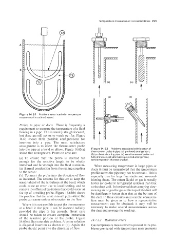
into the pipe at a bend or elbow. Figure 14.63(a) Figure 14.63 Problems associated with location of
shows this arrangement. Points to note are: thermometer probe in pipe: (a) preferred arrangement,
(b) p!obe obstructing pipe, (c) sensitive area of probe not
(a) To ensure that the probe is inserted far fully immersed, (d) alternative preferred arrangement,
sensitive portion of probe shaded.
enough for the sensitive length to be wholly
immersed and far enough into the fluid to minim- When measuring temperature in large pipes or
ize thermal conduction from the sealing coupling ducts it must be remembered that the temperature
to the sensor. profile across the pipe may not be constant. This is
(S) To insert the probe into the direction of flow especially true for large flue stacks and air-cond-
as indicated. The reasons for this are to keep the itioning ducts. The center liquid or gas is usually
sensor ahead of the turbulence at the bend, which hotter (or colder in refrigerated systems) than that
could cause an error due to local heating, and to at the duct wall. In horizontal ducts carrying slow-
remove the effects of cavitation that could occur at moving air or gas the gas at the top of the duct will
the tip of a trailing probe. Figure 14.63(b) shows be significantly hotter than that at Lhe bottom of
the problem that can arise in small pipes where the the duct. In these circumstances careful considera-
probe can cause serious obstruction to the flow. tion must be given as to how a representative
Where it is not possible to put the thermometer measurement can be obtained; it may well be
at a bend in the pipe it can be inserted radially necessary to make several measurements across
provided the pipe is big enough. Great care the duct and average the readings.
should be taken to ensure complete immersion
of the sensitive portion of the probe. Figure
14.63(c) illustrates this problem. A better solution 14.7.2.2 Radiation errors
is diagonal1 insertion as shown at (d). Again the Gas temperature measurements present extra pro-
probe should point into the direction of flow. blems compared with temperature measurements