
Page 337 - Instrumentation Reference Book 3E
P. 337
320 Chemical analysis: spectroscopy
The absorption at the measurement wave- unit amplifies the signal to a suitable level for
length (A,) is compared with the nearby reference transmission to the electronics unit. Between the
wavelength (AnlT) at which the measured compon- lens and the detector module two interference
ent does not absorb. The two measurements are filters, selected for the measurement and refer-
made alternately using a single absorption path ence wavelengths, are interposed alternately in
and the same source and detecting system. the beam, at about 6Hz, so that the detector
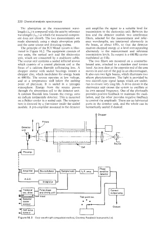
The principle of the IC1 Mond system is illus- receives chopped energy at a level corresponding
trated in Figure 16.2. The equipment consists of alternately to the measurement and reference
two units, the optical unit and the electronics transmission levels. Its output is a 600 Hz carrier
unit, which are connected by a multicore cable. modulated at 6 Hz.
The source unit contains a sealed infrared source The two filters are mounted on a counterba-
which consists of a coated platinum coil at the lanced arm, attached to a stainless steel torsion
focus of a calcium fluoride collimating lens. A band. An iron shoe at the opposite end of the arm
chopper motor with sealed bearings rotates a moves in and out of the gap in an electromagnet.
chopper disc, which modulates the energy beam It also cuts two light beams, which illuminate two
at 600Hz. The source operates at low voltage, silicon phototransistors. The light is provided by
and at a temperature well below the melting two aircraft-type signal lamps which are under-
point of platinum. It is sealed in a nitrogen run to ensure very long life. A drive circuit in the
atmosphere. Energy from the source passes electronics unit causes the system to oscillate at
through the absorption cell to the detector unit. its own natural frequency. One of the photocells
A calcium fluoride lens focuses the energy onto provides positive feedback to maintain the oscil-
an indium antimonide detector. This is mounted lation, and the other provides negative feedback
on a Peltier cooler in a sealed unit. The tempera- to control the amplitude. There are no lubricated
ture is detected by a thermistor inside the sealed parts in the detector unit, and the whole can be
module. A pre-amplifier mounted in the detector hermetically sealed if desired.
n Chopper
unit i Iy
3
Detector
t \ Cell
I I
I I
Figure 16.2 Dual-wavelength comparison method. Courtesy Feedback Instruments Ltd.