
Page 340 - Instrumentation Reference Book 3E
P. 340
Absorption and reflection techniques 323
Reference
Sample
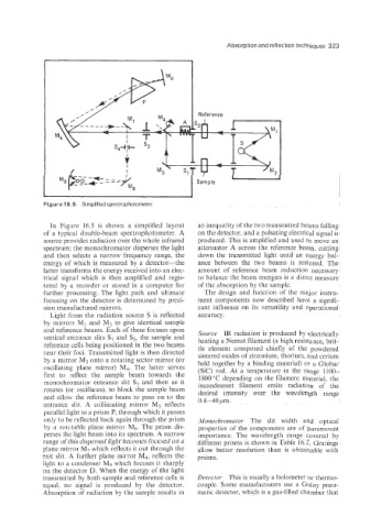
Figure 'I 6.5 Simplified spectrophotometer.
In Figure 16.5 is shown a simplified layout an inequality of the two transmitted beams falling
of a typical double-beam spectrophotometer. A on the detector, and a pulsating electrical signal is
source provides radiation over the whole infrared produced. This is amplified and used to move an
spectrum; the monochromator disperses the light attenuator A across the reference beam. cutting
and then selects a narrow frequency range, the down the transmitted light until an energy bal-
energy of which is measured by a detector-the ance between the two beams is restored. The
latter transforms the energy received into an elec- amount of reference beam reduction necessary
trical signal which is then amplified and regis- to balance the beam energies is a direct measure
tered by a recorder or stored in a computer for of the absorption by the sample.
further processing. The light path and ultimate The design and function of the major instru-
focusing on the detector is determined by preci- ment components now described have a signifi-
sion manufactured mirrors. cant influence on its versatility and operational
Light from the radiation source S is reflected accuracy.
by mirrors MI and M2 to give identical sample
and reference beams. Each of these focuses upon Source IR radiation is produced by electrically
vertical entrance slits SI and S2, the sample and heating a Nernst filament (a high resistance, brit-
reference cells being positioned in the two beams tle element composed chiefly of the powdered
near their foci. Transmitted light is then directed sintered oxides of zirconium, thorium, and cerium
by a mirror M3 onto a rotating sector mirror (or held together by a binding material) or a Globar
oscillating plane mirror) M4. The latter serves (Sic) rod. At a temperature in the range 1100-
first to reflect the sample beam towards the 1800 "C depending on the filament material, the
monochromator entrance slit S; and then as it incandescent filament emits radiation of the
rotates (or oscillates), to block the sample beam desired intensity over the wavelength range
and allow the reference beam to pass on to the 0.4-40 bm.
entrance slit. A collimating mirror M5 reflects
parallel light to a prism P, through which it passes
only to be reflected back again through the prism Monoclzromator The slit width and optical
by a rotztable plane mirror Mg. The prism dis- properties of the components are of paramount
perses the light beam into its spectrum. A narrow importance. The wavelepgth range covered by
range of this dispersed light becomes focused on a different prisms is shown in Table 16.2. Gratings
plane mirror M7 which reflects it out through the allow better resolution than is obtainable with
exit slit. A further plane mirror M8, reflects the prisms.
light to a condenser M9 which focuses it sharply
on the detector D. When the energy of the light
transmitted by both sample and reference cells is Detector This is usually a bolometer or thermo-
equal. no signal is produced by the detector. couple. Some manufacturers use a Colay pnen-
Absorption of radiation by the sample results in matic detector, which is a gas-filled chamber that