
Page 342 - Instrumentation Reference Book 3E
P. 342
Absorption and reflection techniques 325
the intensity at a nearby region where the gas is defined shear by the flue gas. Thus a known and
non-absorbing (B) are alternately measured with fixed path length is provided.
a single detector 40 times per second. Any light When measuring opacity the instrument mea-
level change, whether due to source variation, sures the reduction in transmission in the visible
darkening of the window, scattering by particu- portion of the spectrum.
lates, water drops, or aerosols in the gas stream Typical ranges covered by the instrument are:
affects both A and B, leaving the ratio unchanged.
This ratio gives a reading that is free of interfer- NO 0-25 ppm to 0-5000 ppm
ences. instrumental drift, etc. Most gases obey CO 0-500 ppm to 0-3000 ppm
approximately Beer's law: C02 0-15%
SOz 0-25 ppm to 0-10 000 ppm
B = ~ e ~ ~ ' C-H 0-25 ppm to 0-6000 pplil
H20 0-1000 ppm to 0-80%
01
NH3 0-100ppm
In (BIA) = -ad
or
16.1.3 Absorption in the visible and ultraviolet
ln(AIB)
c=-- Two instruments are worthy of note here. The first
a1 is the Barringer remote sensing correlation spectro-
where 01 is absorption coefficient (known), I is meter designed for the quantitative measurement
path length (fixed), and c is sample concentration of gases such as nitrogen oxides or sulfur dioxide in
(unknown). an optical path between the instrument and a suit-
The system response is almost instantaneous able source of visible and ultraviolet radiant
and is averaged by damping circuits to typically energy. The sensor is designed for maximum ver-
one second. satility in the remote measurement of gas clouds in
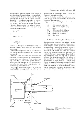
The stack gas is separated from the source and the atmosphere, using the day sky or ground-
analyzer enclosures by means of optical surfaces, reflected solar illumination as the light source. It
such as mirrors or windows. These windows are may also be used with artificial sources such as
kept clean by an air curtain system. Self-con- quartz-iodine or high pressure Xe lamps. Very
tained blowers continually renew the air curtains, simply, the sensor contains two telescopes to collect
preventing the gases from contacting the win- light from a distant source, a two-grating spectro-
dows directly (see Figure 16.7). meter for dispersion of the incoming light, a disc-
The flow volume and pressure of the purge air shaped exit mask or correlator and an electronics
is designed for each application to allow a well system (see Figure 16.8). The slit arrays are
Fan
Window /
Figure 16.7 EDCflue gas analyzer. Courtesy
Filter Environmental Data Corp.