
Page 345 - Instrumentation Reference Book 3E
P. 345
328 Chemical analysis: spectroscopy
Collimating and
telescope lens
\
Reflecting surface
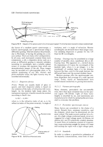
Figure 16.11 Diagram of the optical system of a Littrow spectrograph.The lens has been reversed to reduce scattered light.
the layout of a medium quartz spectroscope, a incidence, and r is angle of refraction. Shorter
Littrow spectrograph, and a spectroscope using a wavelengths are deviated more than longer ones.
diffraction grating. This last employs the principle, The resulting dispersion is greater for the UV
due to Rowland, of having the grating on a con- than for IR wavelengths.
cave surface. There are many other configurations.
In all cases, each instrument contains three main Gratings Gratings may be considered as a large
components, a slit, a dispersive device such as a number of parallel, close, equidistant slits or dif-
prism or diffraction grating to separate radiation fracting lines. The equation nX = 2d sin 0 shows
according to wavelength, and a suitable optical the dependence of 0 upon the wavelength of the
system to produce the spectrum lines which are incident light, where n is an integer, X is the
monochromatic images of the slit. These images wavelength of incident light, d is the distance
may be recorded on a photographic plate, or by between the lines, and 0 is the angle between the
suitable positioning of exit slits, mirrors, and diffracted beam and the normal incident beam.
photo-multiplier tubes, the light intensity may be Modern gratings offer the spectroscopist uni-
recorded electronically.
form dispersion and coverage of a wide spectral
range. Today, nearly all manufacturers have
16.2.1.1 Dispersive devices turned almost exclusively to grating instruments.
Prisms Prisms are usually made of glass or
quartz, and their dispersive ability is based on 16.2.1.2 Vacuum spectrographs
the variation of the index of refraction with wave- Many elements, particularly the non-metallic
length. As the incident light beam enters the ones, have their most persistent lines in the spec-
transparent material, it bends towards the normal tral region 150-220nm. Light of these wave-
according to Snell’s law: lengths is absorbed by air, and instruments are
nlsini=n2sinr manufactured in which the optical paths are evacu-
ated to overcome this problem.
where n1 is the refractive index of air, n2 is the
refractive index of the prism material, i is angle of
16.2.1.3 Excitation: spectroscopic sources
Many factors are considered in the choice of a
source. Sample form, necessary sensitivity, and
the elements, which must be determined, are the
Rowland circle most critical. The main sources used are (a) a d.c.
arc, (b) a high voltage condensed spark, (c) an arc
triggered by a high voltage spark, (d) flames, (e)
plasma jets, and (0 inductively coupled plasmas.
A recent form of excitation consists of evaporat-
ing a non-conducting sample by means of a laser
Slit and exciting the vapor with a high voltage spark.
Grating radius of 16.2.1.4 Standards
curvature
In order to achieve a quantitative estimation of
Figure 16.12 Elementsof Rowland circle the impurity concentrations, some form of stan-