
Page 405 - Instrumentation Reference Book 3E
P. 405
388 Chemical analysis: gas analysis
If the two measurement filaments have a total tors, but is adequate for many applications. The
resistance of R1 and the reference filaments of detector is basically simple, and responds linearly
R2, the output voltage of the bridge E is given by to concentration changes over a wide range. It is
used in gas chromatography and in a variety of
E = I(R1 - R2) (18.6) custom-designed process analyzers.
Combining equations (18.5) and (18.6):
18.3.2 Flame ionization detector @ID)
(18.7)
An extensive group of gas detectors is based on
where K1 and K2 are proportional to the conduct- devices in which changes in ionization current
ivities of the gases in each pair of cells. inside a chamber are measured. The ionization
Equation (18.7) shows that the output is pro- process occurs when a particle of high energy
portional to the cube of the bridge current but in collides with a target particle which is thus
practice the index is usually between I' and 13. ionized. The collision produces positive ions and
For accurate quantitative readings the bridge cur- secondary electrons which may be moved
rent must be kept constant. towards electrodes by application of an electric
This equation also shows that the output is field, giving a measurable current, known as the
proportional to the difference between the reci- ionization current, in the external circuit.
procals of the thermal conductivities of the gases The FID utilizes the fact that, while a hydrogen-
in each pair of cells. This is usually correct for oxygen flame contains relatively few ions
small differences in thermal conductivity but does (lo7 ions ~n-~), does contain highly energetic
it
not hold for large differences. atoms. When trace amounts of organic com-
These conditions show that the katharometer pounds are added to the flame the number of ions
and a
has maximum sensitivity when it is used to meas- increases (to approximately 10" ions ~m-~)
ure the concentration of binary or pseudo-bin- measurable ionization current is produced. It is
ary gas mixtures whose components have widely assumed that the main reaction in the flame is
different thermal conductivities and when the CH+O+CHO+e
bridge current is as high as possible. The max-
imum bridge current is limited by the need to However, the FID gives a small response to sub-
avoid overheating and distortion of the filaments, stances that do not contain hydrogen, such as
and bridge currents can be highest when a gas of CC14 and CS2. Hence it is probable that the reac-
high thermal conductivity is in the cell. When the tion above is preceded by hydrogenation to form
katharometer is used as the detector in gas chro- CH4 or CH3 in the reducing part of the flame. In
matography, hydrogen or helium, which have addition to the ionization reactions, recombina-
higher thermal conductivities than other common tion also occurs, and the response of the FID is
gases, is often used as the carrier gas, and auto- determined by the net overall ionization reaction
matic circuits may be fitted to reduce the current process.
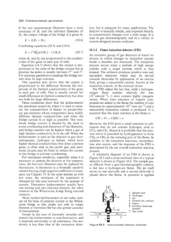
to the bridge to prevent overheating. A schematic diagram of an FID is shown in
For maximum sensitivity, especially when it is Figure 18.5 and a cross-sectional view of a typical
necessary to operate the detector at low tempera- detector is shown in Figure 18.6. The sample gas,
tures, the hot-wire filaments may be replaced by or effluent from a gas-chromatographic column,
thermistors. A thermistor is a thermally sensitive is fed into a hydrogen-air flame. The jet itself
resistor having a high negative coefficient of resist- serves as one electrode and a second electrode is
ance; see Chapter 14. In the same manner as with placed above the flame. A potential is applied
hot wires, the resistance of the conductor is
changed (in this case lowered) by the passage of
current. Thermistor katharometers usually have
one sensing and one reference element, the other
resistors in the Wheatstone bridge being external
1. Sample inlet
resistors. 2. Hydrogen
Many modern katharometers in use today oper- 3. Air
ate on the basis of constant current to the Wheat- 4. Ceramic jet, cathode
stone bridge as this results not only in longer 5. Flame
filament or thermistor life but also greater accuracy 6. Collector electrode
(anode)
of measurement. 7. Gas outlet
Except in the case of thermally unstable sub-
stances the katharometer is non-destructive, and 3 2
it responds universally to all substances. The sen- 1
sitivity is less than that of the ionization detec- Figure 18.5 Flame ionization detector: schematic