
Page 409 - Instrumentation Reference Book 3E
P. 409
392 Chemical analysis: gas analysis
18.3.5 Electron capture detector current and detector temperature must be opti-
mized.
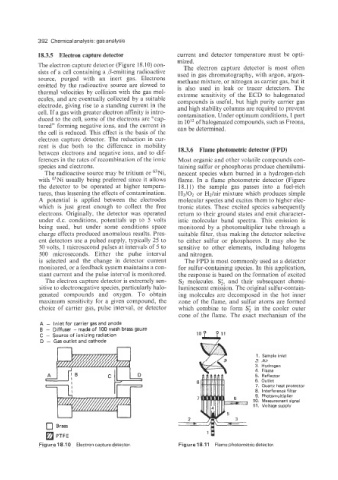
The electron capture detector (Figure 18.10) con- The electron capture detector is most often
sists of a cell containing a P-emitting radioactive used in gas chromatography, with argon, argon-
source, purged with an inert gas. Electrons methane mixture, or nitrogen as carrier gas, but it
emitted by the radioactive source are slowed to is also used in leak or tracer detectors. The
thermal velocities by collision with the gas mol- extreme sensitivity of the ECD to halogenated
ecules, and are eventually collected by a suitable compounds is useful, but high purity carrier gas
electrode, giving rise to a standing current in the and high stability columns are required to prevent
cell. If a gas with greater electron affinity is intro- contamination. Under optimum conditions, 1 part
duced to the cell, some of the electrons are “cap- in 1OI2 of halogenated compounds, such as Freons,
tured” forming negative ions, and the current in can be determined.
the cell is reduced. This effect is the basis of the
electron capture detector. The reduction in cur-
rent is due both to the difference in mobility 18.3.6 Flame photometric detector (FPD)
between electrons and negative ions, and to dif-
ferences in the rates of recombination of the ionic Most organic and other volatile compounds con-
species and electrons. taining sulfur or phosphorus produce chemilumi-
The radioactive source may be tritium or 63Ni, nescent species when burned in a hydrogen-rich
with 63Ni usually being preferred since it allows flame. In a flame photometric detector (Figure
the detector to be operated at higher tempera- 18.11) the sample gas passes into a fuel-rich
tures, thus lessening the effects of contamination. H2/02 or Hz/air mixture which produces simple
A potential is applied between the electrodes molecular species and excites them to higher elec-
which is just great enough to collect the free tronic states. These excited species subsequently
electrons. Originally, the detector was operated return to their ground states and emit character-
under d.c. conditions, potentials up to 5 volts istic molecular band spectra. This emission is
being used, but under some conditions space monitored by a photomultiplier tube through a
charge effects produced anomalous results. Pres- suitable filter, thus making the detector selective
ent detectors use a pulsed supply, typically 25 to to either sulfur or phosphorus. It may also be
50 volts, 1 microsecond pulses at intervals of 5 to sensitive to other elements, including halogens
500 microseconds. Either the pulse interval and nitrogen.
is selected and the change in detector current The FPD is most commonly used as a detector
monitored, or a feedback system maintains a con- for sulfur-containing species. In this application,
stant current and the pulse interval is monitored. the response is based on the formation of excited
The electron capture detector is extremely sen- S2 molecules. S;, and their subsequent chemi-
sitive to electronegative species, particularly halo- luminescent emission. The original sulfur-contain-
genated compounds and oxygen. To obtain ing molecules are decomposed in the hot inner
maximum sensitivity for a given compound, the zone of the flame, and sulfur atoms are formed
choice of carrier gas, pulse interval, or detector which combine to form S; in the cooler outer
cone of the flame. The exact mechanism of the
A - Inlet for carrier gas and anode
B - Diffuser .- made of 100 mesh brass gauze
C - Source of ionizing radiation
D - Gas outlet and cathode lop1
n
1. Sample inlet
2. Air
3. Hydrogen
4. Flame
5. Reflector
6. Outlet
7. Quartz heat protector
8. Interference filter
9. Photomultiplier
10. Measurement signal
11. Voltage supply
0 Brass
PTFE 1U
Figure 18.1 0 Electron capture detector. Figure 18.11 Flame photometric detector.