
Page 414 - Instrumentation Reference Book 3E
P. 414
Process chromatography 397
sequence and to control the apparatus, and a
display or data-processing device to record the
results of the analyses.
18.4.1 Sampling system
The sampling system must present a homo-
geneous and representative sample of the gas or
liquid to be analyzed to the gas chromatograph.
In process chromatography a continuous stream
of the sample is taken, usually by means of a fast
bypass loop, and treated as necessary, for example,
by drying., filtering, or adjustment of temperature
or pressure. Discrete volumes of the treated sam-
ple stream are periodically injected into the car- fa1 Fill
rier gas stream of the chromatograph by means of
a gas (or liquid) sampling valve. The chromato-
graph is normally supplied with the sample from
the point or points to be monitored by use of
permanently installed sampling lines. However,
where the frequency of analysis does not justify
the installation of special lines, samples may be
collected in suitable containers for subsequent
analysis. Gas samples may be collected under
pressure in metal (usually stainless steel) cylinders
or at atmospheric pressure in gas pipettes, gas
sampling syringes, or plastic bags. For analysis
of gases at very low concentrations such as the
determination of pollutants in ambient air, the
pre-column or adsorption tube concentration
technique is often used. The sample is drawn or lb) Inject
allowed to diffuse through a tube containing a
granular solid packing to selectively adsorb the Figure 18.1 8 Gas-sampling valve (schematic)
components of interest. The tube is subsequently
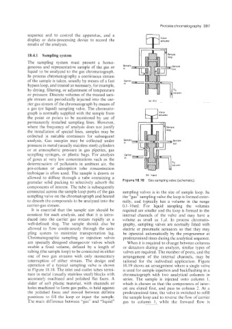
connected across the sample loop ports of the gas sampling valves is in the size of sample loop. In
sampling valve on the chromatograph and heated the “gas” sampling valve the loop is formed exter-
to desorb the compounds to be analyzed into the nally, and typically has a volume in the range
carrier-gas stream. 0.1-10 ml. For liquid sampling the volumes
It is essential that the sample size should be required are smaller and the loop is formed in the
constant for each analysis, and that it is intro- internal channels of the valve and may have a
duced into the carrier gas stream rapidly as a volume as small as 1 pl. In process chromato-
well-defined slug. The sample should also be graphy, sampling valves are normally fitted with
allowed to flow continuously through the sam- electric or pneumatic actuators so that they may
pling system to minimize transportation lag. be operated automatically by the programer at
Chromatographic sampling or injection valves predetermined times during the analytical sequence.
are specially designed changeover valves which When it is required to change between columns
enable a fixed volume, defined by a length of or detectors during an analysis, similar types of
tubing (the sample loop) to be connected in either valves are required. The number of ports, and the
one of two gas streams with only momentary arrangement of the internal channels, may be
interruption of either stream. The design and tailored for the individuai application. Figure
operation of a typical sampling valve is shown 18.19 shows an arrangement where a single valve
in Figure 18.18. The inlet and outlet tubes termi- is used for sample injection and backflushing in a
nate in metal (usually stainless steel) blocks with chromatograph with two analytical columns in
accurately machined and polished flat faces. A series. The sample is injected onto column 1.
slider of soft plastic material, with channels or which is chosen so that the components of inter-
holes machined to form gas paths, is held against est are eluted first, and pass to column 2. At a
the polished faces and moved between definite predetermined time, the valve is switched to refill
positions to fill the loop or inject the sample. the sample loop and to reverse the flow of carrier
The main difference between ”gas” and “liquid” gas to column 1, while the forward flow is