
Page 415 - Instrumentation Reference Book 3E
P. 415
398 Chemical analysis: gas analysis
Actuator Actuator
Sample
Sample loop F loop
(a) Inject lbl Backflush
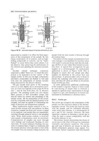
Figure 18.19 Schematic diagram of sample and backflush valve.
maintained in column 2 to effect the final separ- sample from the next stream is flowing through
ation of the components of the sample. By this all common lines.
means components of no interest, such as high- Prevention of inter-sample contamination from
boiling compounds or solvents, can be “back- valve leakage is accomplished by locating valves
flushed” to waste before they reach column 2 or with respect to pressure drops such that any leak-
the detector, thus preserving the performance of age will flow to vent rather than intermix in com-
the columns and speeding the analytical proced- mon lines. A typical flow arrangement for gas
ure. supplies to a chromatograph for multi-stream
Another related technique commonly application is shown in Figure 18.20. This is
employed is called “heart cut,” in which the com- designed to ensure that the sample and other
ponent to be analyzed is in the “center” of the supplies are delivered at the correct flow rate
sample profile. In this case the light components and pressure. A pressure-relief valve is fitted to
and heavy components are flushed to vent and protect the sampling valve from excessive pres-
with only the components of interest actually sure, and shut-off valves are fitted on all services
being measured by the detector element. except bottled gas lines.
The gas sample must arrive at the sampling In some applications additional conditioning
valve at or only slightly above atmospheric pres- of the sample is required. Typical of these would
sure, at a flow rate typically in the range 10-50 ml be trace-heating of sample lines to maintain a
min-’, and be free from dust, oil, or abrasive sample in a gaseous state, vaporization to change
particles. The sampling system may also require a liquid to a gas. and elimination of stream con-
filters, pressure or flow controllers, pumps, and taminants by mechanical or chemical means.
shut-off valves for control and processing of the
sample stream. All the components of the system
must be compatible with the chemical species to be 18.4.2 Carrier gas
sampled, and must be capable of withstanding the The carrier gas transports the components of the
range of pressures and temperatures expected. sample over the stationary phase in the chroma-
Many applications require analysis of two or tographic column. The carrier gas must not react
more process streams with one analyzer. In these with the sample, and for maximum efficiency
instances a sample line from each stream is piped when using long columns. it is advantageous to
to the analyzer, and sample lines are sequentially use a gas of low viscosity. However, the most
switched through solenoid valves to the sampling important criterion in choosing a carrier gas is
valve. When multi-stream analysis is involved, often the need to ensure compatibility with the
inter-sample contamination must be prevented. particular detector in use.
Contamination of samples can occur through The primary factors determining the choice of
valve leakage and inadequate flushing of com- carrier gas are the effect of the gas on component
mon lines. To ensure adequate flushing, the cap- resolution and detector sensitivity. The carrier
acity of common lines is kept to a minimum and gas and type of detector are chosen so that the
the stream selection valves are timed so that while eluted components generate large signals. For
the sample from one stream is being analyzed, the this reason, helium is generally used with thermal