
Page 420 - Instrumentation Reference Book 3E
P. 420
Process chromatography 403
the peaks in a chromatogram. The area is obtained 18.4.8 Operation of a typical process
by summation of a number of individual measure- chromatograph
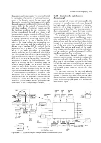
ments of the detector output during a peak, and As an example of process chromatography, the
the number reported by the integrator is typically operation of a single-stream instrument designed
the peak area expressed in millivolt-seconds. Inte- for high-speed on-line measurement of the con-
grators differ in the method of processing the centration of a single component. or group of
individual readings of detector output, and in components, is described. The chromatograph is
the facilities available in the instrument for shown schematically in Figure 18.23, and consists
further processing of the peak area values. In all of an analyzer, a processor, and a power unit.
instruments the analog output signal from the gas The analyzer unit contains those parts of the
chromatograph is first converted to digital form. system required for sample handling and separ-
In simpler integrators an upward change in the ation and detection of the components. There is a
baseline level, or in the rate of baseline drift, is single column and thermal conductivity detector
taken as the signal to begin the summation pro- housed in a temperature-controlled zone at the
cess, which continues until the baseline level, or a top of the unit, with the associated electronics
defined rate of baseline drift, is regained. As the beneath. The packing and length of the srnall-
instrument has to be aware of the baseline change bore column are chosen to suit the application.
before it can begin integration, a proportion, and the carrier-gas regulator is designed for high
usually negligibly small, of each peak is inevitably stability under low-flow conditions.
lost, the amount depending on the settings of the The small-volume thermal ccnducti1,ity type
slope sensitivity and noise-rejection controls. This detector uses thermistor elements to produce the
difficulty is obviated in the so-called “computing” output signals with high speed and stability. The
integrators by storing the digitized detector read- electronic circuit modules mounted in the lower
ings in a memory so that a complete peak, or half of the main case control the oven tempera-
series of merged peaks, can be stored and inte- ture, power the detector, and amplify its output,
grated retrospectively. Baseline assignment can and provide power pulses to operate the valve
then also be made retrospectively. In the most solenoids.
sophisticated models the memory is large enough The processor contains the electronic circuits
to store data corresponding to a complete chro- which control the sequentid operation of the total
matogram. Use is also made of the memory to system. It times the operation of the simple injec-
provide facilities for automatic computation of tion and column switching valves, selects and inte-
calibration ‘curves, and the integrator may then grates a chromatographic peak, and updates the
provide a printed output record giving the con- trend output signal.
centrations of each component of interest.
Figure 18.23 Schematic diagram of single-channel process chromatograph