
Page 421 - Instrumentation Reference Book 3E
P. 421
404 Chemical analysis: gas analysis
Reference Trigger
peak peak Marker pips at steps 2.3, 5,6,9, and 10
Coarse Backflushed
auto
______
auto
’ injection
.-Corrected retention time- Backflush time
Ratio-time mode e I , t 11 ~Component retention time
Component
width time,
1.e..
lntegrmmn
~
window
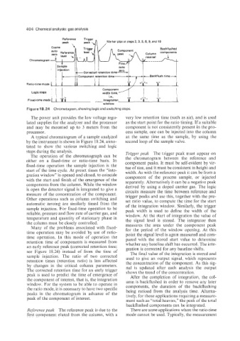
Figure 18.24 Chromatogram, showing logic and switching steps.
The power unit provides the low voltage regu- very low retention time (such as air), and is used
lated supplies for the analyzer and the processor as the start point for the ratio timing. If a suitable
and may be mounted up to 3 meters from the component is not consistently present in the pro-
processor. cess sample, one can be injected into the column
A typical chromatogram of a sample analyzed at the same time as the sample, by using the
by the instrument is shown in Figure 18.24, anno- second loop of the sample valve.
tated to show the various switching and logic
steps during the analysis. Trigger peak The trigger peak must appear on
The operation of the chromatograph can be the chromatogram between the reference and
either on a fixed-time or ratio-time basis. In component peaks. It must be self-evident by vir-
fixed-time operation the sample injection is the tue of size, and it must be consistent in height and
start of the time cycle. At preset times the “inte- width. As with the reference peak it can be from a
gration window” is opened and closed, to coincide component of the process sample, or injected
with the start and finish of the emergence of the separately. Alternatively it can be a negative peak
components from the column. While the window derived by using a doped carrier gas. The logic
is open the detector signal is integrated to give a circuits measure the time between reference and
measure of the concentration of the component. trigger peaks and use this, together with the pre-
Other operations such as column switching and set ratio value, to compute the time for the start
automatic zeroing are similarly timed from the of the integration window. Similarly, the trigger
sample injection. For fixed-time operation to be peak width is used to define the width of the
reliable, pressure and flow rate of carrier gas, and window. At the start of integration the value of
temperature and quantity of stationary phase in the signal level is stored. The integrator then
the column must be closely controlled. measures the area under the component peak
Many of the problems associated with fixed- for the period of the window opening. At this
time operation may be avoided by use of ratio- point the signal level is again measured and com-
time operation. In this mode of operation the pared with the stored start value to determine
retention time of components is measured from whether any baseline shift has occurred. The inte-
an early reference peak (corrected retention time; gration is corrected for any baseline shifts.
see Figure 18.24) instead of from the time of The final value of the integration is stored and
sample injection. The ratio of two corrected used to give an output signal, which represents
retention times (retention ratio) is less affected the concentration of the component. As this sig-
by changes in the critical column parameters. nal is updated after each analysis the output
The corrected retention time for an early trigger shows the trend of the concentration.
peak is used to predict the time of emergence of After the completion of integration, the col-
the component of interest, that is, the integration umn is backflushed in order to remove any later
window. For the system to be able to operate in components, the duration of the backflushing
the ratio mode, it is necessary to have two specific being ratioed from the analysis time. Alterna-
peaks in the chromatogram in advance of the tively, for those applications requiring a measure-
peak of the component of interest.
ment such as “total heavies,” the peak of the total
backflushed components can be integrated.
Reference peak The reference peak is due to the There are some applications where the ratio-time
first component eluted from the column, with a mode cannot be used. Typically, the measurement