
Page 424 - Instrumentation Reference Book 3E
P. 424
Special gas analyzers 407
18.5.1.3 Quincke analyzer carrier gas producing a change in its thermal
conductivity. These difficulties led to the devel-
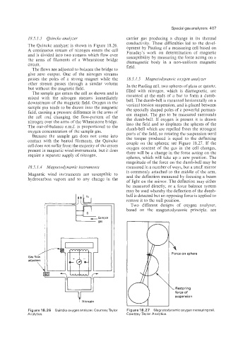
The Quincke analyzer is shown in Figure 18.26. opment by Pauling of a measuring cell based on
A continuous stream of nitrogen enters the cell Faraday’s work on determination of magnetic
and is divided into two streams which flow over susceptibility by measuring the force acting on a
the arms of filaments of a Wheatstone bridge diamagnetic body in a non-uniform magnetic
circuit. field.
The flows are adjusted to balance the bridge to
give zero output. One of the nitrogen streams
passes the poles of a strong magnet while the 18.5.1.5 Magnetodynamic oxygen aiialyzer
other stream passes through a similar volume In the Pauling cell, two spheres of glass or quartz.
but without the magnetic field. filled with nitrogen. which is diamagnetic, are
The sample gas enters the cell as shown and is mounted at the ends of a bar to form a dumb-
mixed with the nitrogen streams immediately bell. The dumb-bell is mounted horizontally on a
downstream of the magnetic field. Oxygen in the vertical torsion suspension, and is placed between
sample gas tends to be drawn into the magnetic the specially shaped poles of a powerful perman-
field, causing a pressure difference in the arms of ent magnet. The gas to be measured surrounds
the cell 2nd changing the flow-pattern of the the dumb-bell. If oxygen is present it is drawn
nitrogen over the arms of the Wheatstone bridge. into the field and so displaces the spheres of the
The out-of-balance e.m.f. is proportional to the dumb-bell which are repelled from the strongest
oxygen concentration of the sample gas. parts of the field, so rotating the suspension until
Because the sample gas does not come into the torque produced is equal to the deflecting
contact with the heated filaments, the Quincke couple on the spheres: see Figure 18.27. If the
cell does not suffer from the majority of the errors oxygen content of the gas in the cell changes,
present in magnetic wind instruments, but it does there will be a change in the force acting on the
require a separate supply of nitrogen. spheres, which will take up a new position. The
magnitude of the force on the dumb-bell may be
18.5.1.4 Magnetodynamic imstrumeuts measured in a number of ways, but a small mirror
is commonly attached to the middle of the arm,
Magnetic wind instruments are susceptible to and the deflection measured by focusing a beam
hydrocarbon vapors and to any change in the of light on the mirror. The deflection may either
be measured directly, or a force balance system
may be used whereby the deflection of the dumb-
bell is detected but an opposing force is applied to
restore it to the null position.
Two different designs of oxygen analyzer,
based on the magnetodynamic principle. are
Force on sphere
LT L Restoring
force of
suspension
t Nitrogen
Figure 18.26 Quincke oxygen analyzer. Courtesy Taylor Figure 18.27 Magnetodynamic oxygen measuring cell.
Analytics. Courtesy Taylor Analytics.