
Page 429 - Instrumentation Reference Book 3E
P. 429
412 Chemical analysis: gas analysis
where R1 is permeation rate at TiK and Rz is stream of a second gas through the vessel at a
permeation rate at T3K. The permeation rate constant flow rate. It can be shown that, under
changes by approximately 10 percent for every these conditions, the concentration of any gas-
1 K change in temperature. Thus, the temperature eous species in the vessel, and hence the instanta-
of the permeation tube must be controlled to neous concentration in the effluent stream of
within 0.1 K or better if 1 percent accuracy in diluent gas, decays according to the law
the permeation rate, and thus the concentration
that is being developed, is to be achieved.
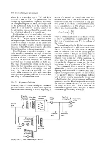
The flow diagram of a typical calibrator for use
with diffusion or permeation tubes is shown in where Cis the concentration of the diluted species
Figure 18.33. The gas supply is scrubbed before at time t, CO is the initial concentration, U is the
passing through a thermostatted coil and over the flow rate of diluent gas, and V is the volume of
calibration source or sources in the calibration the vessel.
chamber. Secondary streams of purified gas may The vessel may either be filled with the gaseous
be added to the effluent gas stream to adjust the species to be analyzed, in which case the concen-
final concentration to the range required. tration decays from an initial value of 100 per-
The diffusion or permeation technique is espe- cent, or it may be filled with the diluent gas and
cially useful for generating standard mixtures at a known volume of the gas of interest may be
low concentrations, for example of organic com- injected into the diluent gas just upstream of the
pounds in air for calibration of environmental dilution vessel at the start of the experiment. In
monitors, air pollution monitors, etc., and the either case the concentration of the species of
calibrator can be made portable for field use. interest in the effluent gas stream may be calcu-
The range of compounds, which can be used, is lated at any time after the start of the dilution.
limited by their saturation vapor pressure; if this The exponential dilution vessel is typically a
is too low, the diffusion or permeation rates, and spherical or cylindrical glass vessel of 25Ck500ml
hence the concentrations available, are very capacity, fitted with inlet and outlet tubes, and a
small, while compounds with high saturation septum cap or gas sampling valve for introduction
vapor pressures present problems in construction of the gas to be diluted. The vessel must be fitted
and filling of the calibration tubes. with a stirrer, usually magnetically driven, and
baffles to ensure that mixing is as rapid and homo-
geneous as possible. The diluent gas flows through
18.6.2.3 Exponential dilution the vessel at a constant known flow rate, usually in
In the exponential dilution technique a volume of the range 20-30ml min-'. For a vessel of the
gas contained in a vessel, in which there is perfect dimensions suggested above, this gives a tenfold
and instantaneous mixing, is diluted by passing a dilution in approximately 30 minutes.
Figure 18.33 Flowdiagramofgas calibrator.