
Page 426 - Instrumentation Reference Book 3E
P. 426
Calibration of gas analyzers 409
automatic electronic subtraction of the NO con-
centration from the NO, value.
The flow system of a nitrogen oxides analyzer
is shown in Figure 18.31. Ozone is generated from
ambient air by the action of W light
hV
3024203
and a controlled flow rate of ozonized air is
passed to the reaction chamber for reaction with
Check valve
CH in- 150cctank NO in the air sample, which is passed through the
24
Pressure chamber at a controlled flow of 1 lmin-’. By
ia) gauge
selection of a switch to operate the appropriate
solenoid valves. a span gas may be directed to the
Buff
reaction chamber, or a zero calibration may be
carried out by shutting off the flow of ozonized
air to the reactor. The three-way solenoid valve
downstream of the converter is switched to per-
mit NO analysis when bypassing the converter,
and NO, analysis when the sample is passed
through the converter. The analyzer can measure
ozone in air in the range 5 ppb to 25 ppm, with a
precision of fl percent.
yeze
Thermistor Sohd 18.5.4 Summary of special gas analyzers
temperature SUPP~ WlW
control The operating principles of analyzers for the most
Ibl commonly measured gases are given in Table
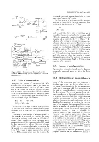
Figure 18.30 Ozone analyzer. Courtesy Columbia
Scientific Industries Corp.: (a) flow diagram, (b) functional 18.4.
block diagram.
18.6 Calibration of gas analyzers
es of nitrogen analyzer
None of the commonly used gas detectors is
Analyzers for oxides of nitrogen-NO, NO, absolute; that is, they are devices where the out-
(total oxides of nitrogen), NO2 - are based on put signal from the detector for the gas mixture
the chemiluminescent reaction of nitric oxide under test is compared with that for mixtures of
(NO) and ozone to produce nitrogen dioxide the bulk gas containing known concentrations of
(NO2). About 10 percent of the NO2 is produced the determinand. The use of standard gas mix-
in an electronically excited state, and undergoes a tures is analogous to the use of standard solutions
transition to the ground state, emitting light in in solution chemistry, but their preparation and
the wavelength range 590-2600 nm: handling present some peculiar problems. As in
NO+03 4 NO;+02 solution chemistry, the calibration gas mixtures
should reflect, as closely as possible, the compos-
NO; + NO2 + IZV ition of the samples they are desired to measure.
The intensity of the light emission is proportional Ideally a number of standard mixtures. whose
to the mass-flow rate of NO through the reaction concentration covers the range of samples to be
chamber and is measured by a photomultiplier measured, should be used to establish the
tube. response curve of the instrument or detector.
Analysis of total oxides of nitrogen (NO,) in However, for routine calibration where the
the sample is achieved by passing the gases response curve has previously been established
through a stainless steel tube at 600-800°C. or is well known. it is usual to calibrate gas ana-
Under these conditions, most nitrogen com- lyzers by use of a “zero” gas mixture which is free
pounds (but not N20) are converted to NO which of the determinand and es’zablishes the zero of the
is then measured as above. Nitrogen dioxide instrument, and one or more “span” gases contain-
(NO21 may be measured directly by passing the ing concentrations of the determined close to
air sample over a molybdenum catalyst to reduce those it is desired to measure.
it to NO, which is again measured as above, The accuracy to which a gas mixture can be
or the NO2 concentration may be obtained by prepared depends on the number and nature of