
Page 445 - Instrumentation Reference Book 3E
P. 445
428 Electrical measurements
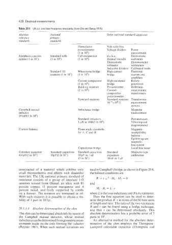
Table 20.1 UK d.c. and low-freuqency standards (from Dix and Bailey 1975)
Absolute Nut ional Other national standards apparatus
reference primary
standards standards
Diesselhorst Volt ratio box
potentiometer Voltage dividers Power
(1 in lo8) measurement
Josephson-junction Standard cells Cell comparator d.c.1a.c. Electrostatic
system (1 in io7) (3 in lo8) (1 in lo8) thermal transfer wattmeter
Electrostatic Dynamometer
voltmeter wattmeters
Inductive dividers Calibrated loads
Standard 1R Wheatstone bridge High-current Electronic
resistors (1 in io7) (1 in lo8) bridge sources and
amplifiers
Current comparator High-resistance Rotary
(1 in IO8) bridge generators
Build-up resistors Potentiometer Reference-
(2 in IO*) Current- measurement
comparator transformers
potentiometer
Standard resistors Standard resistors Transformer-
10-~-10~ R measurement
systems
Campbell mutual Inductance bridge Magnetic
inductor measurement
lOmH(1 in lo6)
Standard inductors Permeameters
1 pH to lOH(2 in 10’) Vibrating-coil
magnetometer
Current balance Phase-angle standards Magnetic-
for L, C and R susceptibility
balance
Epstein-square
magnetic-
loss system
Capacitance bridge Local-loss tester
Calculate capacitor Standard capacitors Standard capacitors Standard Magnetic-tape
0.4pF(2 in 10’) lOpF(2 in 10’) lOpF to 1nF capacitors calibration
(5 in io7) lOnF to 1 LLF
constructed of a material which exhibits only used in Campbell’s bridge. as shown in Figure 20.6,
small thermoelectric emf effects with dissimilar the balance conditions are
materials. The UK national primary standard of R.I‘+w”MI .M?=O
resistance consists of a group of standard 1-0
resistors wound from Ohmal, an alloy with 85 and
percent copper, 11 percent manganese and 4
percent nickel, and freely supported by combs 1441 . R, = L . I’
on a former. The resistors are immersed in oil. where Lis the loop inductance and R is its resistance.
With such resistors it is possible to obtain a sta- Thus the first equation can be used to deter-
bility of 1 part in 107/yr. mine the product R ’ I’ in terms of the SI base units
of length and time. The ratio of the two resistances
R and I’ can be found using a bridge technique.
20.1.3.4 Absolute determii~ation of the olzin
and thus I‘ can be determined absolutely. This
The ohm can be determined absolutely by means of absolute determination has a probable error of 2
the Campbell mutual inductor, whose mutual parts in IO6.
inductance can be determined from geometric meas- An alternative method for the absolute deter-
urements made on the coils forming the inductor mination of the ohm employs the Thompson-
(Rayner 1967). When such mutual inductors are Lampard calculable capacitor (Thompson and