
Page 448 - Instrumentation Reference Book 3E
P. 448
Measurement of d.c. and ax. current and voltage using indicating instruments 431
I I
Electrodes
s;”d’
Calculable
capacitor
0.2 - 0.6 PF
20: 1 to 50: 1
t voltage transformer bridge
t 10: 1 voltage transformer bridge
Length I Quadrature bridge
change AL 100 kC2
determined 1000 pF L (ax.)
r
optically
Movable
guard
electrode
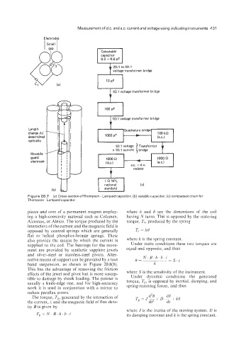
Figure 20.7 (a) Cross-section ofThompson-Lampard capacitor; (b) variable capacitor; (c) comparison chain for
Thoimpson- Lampard capacitor.
pieces and core of a permanent magnet employ- where 11 and b are the dimensions of the coil
ing a high-coercivity material such as Columax, having N turns. This is opposed by the restoring
Alcomax, or Alnico. The torque produced by the torque, T,, produced by the spring
interactioa of the current and the magnetic field is
opposed by control springs which are generally T, = Ice
flat or helical phosphor-bronze springs. These
also provide the means by which the current is where k is the spring constant.
snpplied to the coil. The bearings for the move- Under static conditions these two torques are
ment are provided by synthetic sapphire jewels equal and opposite, and thus
and silver-steel or stainless-steel pivots. Alter-
native means of support can be provided by a taut 8= N. B.11. b. i =S.i
band suspension, as shown in Figure 20.8(b). k
This has ithe advantage of removing the friction
effects of the jewel and pivot but is more suscep- where S is the sensitivity of the instrument.
tible to damage by shock loading. The pointer is Under dynamic conditions the generated
usually a knife-edge one, and for high-accuracy torque, TE, is opposed by inertial, damping, and
work it is used in conjunction with a mirror to spring-restoring forces, and thus
reduce parallax errors.
The torque, T,, generated by the interaction of d’B dQ
dt
the current, i, and the magnetic field of flux dens- T, = J- dt2 + D . - + k0
ity B is given by
where J is the inertia of the moving system, D is
T, = N. B. h, b . i its damping constant and k is the spring constant.