
Page 453 - Instrumentation Reference Book 3E
P. 453
436 Electrical measurements
a.c. 8.0. a.c.
iov 6WV 3WV
d.c. a.c. d.c.
1oov
a.c.
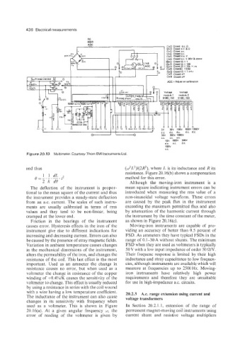
Figure 20.13 Multimeter. Courtesy Thorn EM1 Instruments Ltd.
and thus (w2L2)/(2R2), where L is its inductance and R its
resistance. Figure 20.16(b) shows a compensation
0 1 1 dL .2 method for this error.
2 k d0 Although the moving-iron instrument is a
The deflection of the instrument is propor- mean square indicating instrument errors can be
tional to the mean square of the current and thus introduced when measuring the rms value of a
the instrument provides a steady-state deflection non-sinusoidal voltage waveform. These errors
from an a.c. current. The scales of such instru- are caused by the peak flux in the instrument
ments are usually calibrated in terms of rms exceeding the maximum permitted flux and also
values and they tend to be non-linear, being by attenuation of the harmonic current through
cramped at the lower end. the instrument by the time constant of the meter,
Friction in the bearings of the instrument as shown in Figure 20.16(c).
causes error. Hysteresis effects in the iron of the Moving-iron instruments are capable of pro-
instrument give rise to different indications for viding an accuracy of better than 0.5 percent of
increasing and decreasing current. Errors can also FSD. As ammeters they have typical FSDs in the
be caused by the presence of stray magnetic fields. range of 0.1-30 A without shunts. The minimum
Variation in ambient temperature causes changes FSD when they are used as voltmeters is typically
in the mechanical dimensions of the instrument, 50V with a low input impedance of order 50 ON.
alters the permeability of the iron, and changes the Their frequenc response is limited by their high
resistance of the coil. This last effect is the most inductance and stray capacitance to low frequen-
important. Used as an ammeter the change in cies, although instruments are available which will
resistance causes no error, but when used as a measure at frequencies up to 2500Hz. Moving-
voltmeter the change in resistance of the copper iron instruments have relatively high power
winding of +0.4%/K causes the sensitivity of the requirements and therefore they are unsuitable
voltmeter to change. This effect is usually reduced for use in high-impedance ax. circuits.
by using a resistance in series with the coil wound
with a wire having a low temperature coefficient. 20.2.3 A.c. range extension using current and
The inductance of the instrument can also cause voltage transformers
changes in its sensitivity with frequency when
used as a voltmeter. This is shown in Figure In Section 20.2.1.1, extension of the range of
20.16(a). At a given angular frequency i~, the permanent magnet-moving coil instruments using
error of reading of the voltmeter is given by current shunt and resistive voltage multipliers