
Page 455 - Instrumentation Reference Book 3E
P. 455
438 Electrical measurements
Table 20.5 Electronic multimeter specification
D. c. voltmeter
Voltage ranges: f 15 mV to f 1500 V full scale in 15, 50 sequence (1 1 ranges)
Accuracy: f2% of full scale on any range
Input resistance: 100 Mn ?C 1% on 500mV range and above, IOMR f 3% on 150mV range and below
A. c. voltnzeter
Voltage ranges: 0.5V to 300V full scale in 0.5, 1.5, 5 sequence (7 ranges)
Frequency range: 20 Hz to 700 MHz
Accuracy: &3% of full scale at 400 Hz for sinusoidal voltages from 0.5 V-300 V rms. The a.c. probe responds to the
positive peak-above-average value of the applied signal. The meter is calibrated in rms
Frequency response: ?C2% from 100 Hz to 50 MHz (400 Hz ref.); 0 to -4% from 50 MHz to 100 MHz; &lo% from
20Hz to 100Hz and from 100MHz to 700MHz
Input impedance; input capacitance 1.5 pF. input resistance > 10 MR at low frequencies. At high frequencies,
impedance drops off due to dielectric loss
Safety: the probe body is grounded to chassis at all times for safety. All a.c. measurements are referenced to chassis
ground
D. c. ammeter
Current ranges: 51.5 pA to Ik150mA full scale in 1.5, 5 sequence (1 1 ranges)
Accuracy: &3% of full scale on any range
Input resistance: decreasing from 9 kR on 1.5pA range to approximately 0.3 R on the 150mA range
Special current ranges: +1.5,f5 and *15pA may be measured on the 15, 50, and 150mV ranges using the d.c
voltmeter probe, with &5% accuracy and lOMR input resistance
Olimmeter
Resistance range: resistance from 100 to 10Ma center scale (7 ranges)
Accuracy: zero to midscale: Ik5% of reading of &2Yo of midscale, whichever is greater; Ik7% from midscale to scale
value of 2; &8% from scale value of 2 to 3; &9yo from scale value to 3 to 5; 510% from scale value of 5 to IO
Maximum input: d.c.: IOOV on 15, 50 and 150mV ranges, 500V on 0.5 to 15V ranges, 1600V on higher ranges.
As.: 100 times full scale or 450V p, whichever is less
construction minimizes the magnetizing current,
iron loss, and leakage flux, ensuring that the actual
Pointer
primary to secondary current ratio is close to the
er inverse-turns ratio.
Figure 20.17(c) shows the effect of magnetizing
current and iron loss on the relative magnitudes
and phases of the primary and secondary cur-
rents.
Two errors of cts can be identified in Figure
20.17(c). These are the current or ratio error and
the phase angle error or phase displacement. The
current or ratio error is defined as
Rated ratio (Zplls) - actual ratio (Zp/ls)
Actual ratio (Zplls) x 100%
The phase-angle error or phase displacement is the
phase angle between the primary and secondary
current phasors drawn in such a way (as in Figure
20.1 7(c)) that for a perfect transformer there is zero
phase displacement. When the secondary current
leads the primary current the phase displacement is
positive.
These errors are expressed with respect to a
particular secondary load which is specified by
its burden and power factor. The burden is the
VA rating of the instrument at full load current.
chamber A typical burden may be 15 VA with a power
(b) factor of 0.8 lagging. Figure 20.17(d) shows typ-
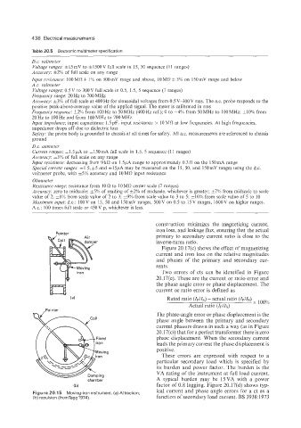
Figure 20.15 Moving-iron instrument. (a) Attraction; ical current and phase angle errors for a ct as a
(b) repulsion (fromTagg1974). function of secondary load current. BS 3938:1973