
Page 458 - Instrumentation Reference Book 3E
P. 458
Measurement of d.c. and ax. current and voltage using indicating instruments 441
Flux in
oltmeter
"P "s
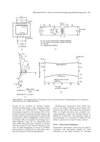
Rp, RS: primary and secondary winding resistances
X,, Xs: primary and secondary leakage impedances
Re: iron loss
X, : magnetizing impedance
a.c. voltmeter
i bl
Voltage error
+0.15 r 1%) 1
+0.2
Measured under no-load
conditions
I I I -0.6
10 20 40 60 80 100
Full rated
secondary voltage (%)
Phase-angle error =6 AOB
(cl
Figure 20.1 8 (a) Voltage transformer; (b) equivalent circuit; (c) phasor diagram of voltage transformer; (d) voltage and
phase-ang'e errors for voltage transformer.
having its hot junction in thermal contact Thermocouple instruments have FSDs typ-
with the heating element; and a permanent mag- ically in the range 2-50mA and are usually cali-
net-moving coil millivoltmeter. Thermocouple brated in rms values. The scale is thus non-linear.
instruments respond to the heating effect of the They are fragile and have only a limited over-
current passing through the heating element and range capability before the heating element is
are thus mean-square sensing devices and provide melted by overheating. The frequency range of
an indication which is independent of the current the instrument as a voltmeter is limited by the
waveshape. They are capable of operating over a ability to produce non-reactive series resistors.
wide frequency range. At low frequencies (less
than 10 Hz) their operation is limited by pointer
vibration caused by the thermal response of the 20.2.6 Electrostatic instruments
wire. At high frequencies (in excess of 10MHz) Electrostatic instruments which may be used as
their operation is limited by the skin effect alter- voltmeters and wattmeters depend for their
ing the resistance of the heating element. operation on the forces between two charged