
Page 459 - Instrumentation Reference Book 3E
P. 459
442 Electrical measurements
range 100-1000 V. Electrostatic instruments have
the advantage of a capacitive high input imped-
ance. They are fragile and expensive, and there-
fore their use is limited to that of a transfer
standard between a.c. and d.c. quantities.
20.3 Digital voltmeters and
digital multimeters
Analog indicating instruments provide a simple
and relatively cheap method of indicating trends
and changes in measured quantities. As volt-
meters, direct indicating instruments have low
Fixed coil1-' Fixed coil input impedance. At best they provide only
ti? t limited accuracy, and this is achieved only with
Figure 20.19 Dynamometer instrument. considerable skill on the part of the observer.
Their speed of response is also slow. Digital
instruments, in contrast, can provide high input
Heater impedance, high accuracy and resolution, and a
high speed of measurement. They provide an
indication to the observer which is free from
ambiguity and requires no interpolation.
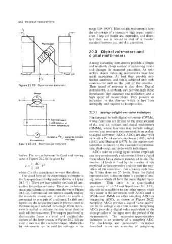
Thermocouple
20.3.1 Analog-to-digital conversion techniques
Fundamental to both digital voltmeters (DVMs),
1 Terminal block: whose functions are limited to the measurement
I cold junction at
J room temperature of d.c. and as. voltage, and digital multimeters
(DMMs), whose functions may include voltage,
current, and resistance measurement, is an analog-
to-digital converter (ADC). ADCs are dealt with
Output a i2Rh: scaled to indicate in detail in Part 4 and also in Owens (1983), Arbel
Microammeter rms value
(1980), and Sheingold (1977). In this section con-
Figure 20.20 Thermocouple instrument. sideration is limited to the successive-approxima-
tion, dual-ramp, and pulse-width techniques.
ADCs take an analog signal whose amplitude
bodies. The torque between the fixed and moving can vary continuously and convert it into a digital
vane in Figure 20,21(a) is given by form which has a discrete number of levels. The
number of levels is fixed by the number of bits
employed in the conversion and this sets the reso-
lution of the conversion. For a binary code hav-
where C is the capacitance between the plates. ing N bits there are 2N levels. Since the digital
The usual form of the electrostatic voltmeter is representation is discrete there is a range of ana-
the four-quadrant configuration shown in Figure log values which all have the same digital repre-
20.21(b). There are two possible methods of con- sentation, Thus there is a quantization
nection for such a voltmeter. These are the hetero- uncertainty of &1/2 Least Significant Bit (LSB),
static and idiostatic connections shown in Figure and this is in addition to any other errors which
20.21 (c). Commercial instruments usually employ may occur in the conversion itself. ADCs used in
the idiostatic connection, in which the needle is DVMs and DMMs are either sampling ADCs or
connected to one pair of quadrants. In this con- integrating ADCs, as shown in Figure 20.22.
figuration the torque produced is proportional to Sampling ADCs provide a digital value equiva-
the mean square value of the voltage. If the instru- lent to the voltage at one time instant. Integrating
ment is scaled to indicate the rms value then the ADCs provide a digital value equivalent to the
scale will be non-linear. The torques produced by average value of the input over the period of the
electrostatic forces are small and multicellular measurement. The successive-approximation
devices of the form shown in Figure 20.21(d) are technique is an example of a sampling ADC.
used to increase the available torque. Multicellu- The dual-ramp and pulse-width techniques
lar instruments can be used for voltages in the described below are examples of integrating