
Page 463 - Instrumentation Reference Book 3E
P. 463
446 Electrical measurements
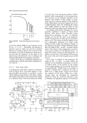
, Series Mode Rejection (dB) it at the end of the conversion period a binary
number which corresponds to the analog input.
The accuracy of the technique depends on the
linearity and stability of the voltage to pulse-
width converter and the stability of the reference
clock. High-speed conversion requires the use of
a high-frequency clock. By summing the counts
over longer periods of time the effect of line
frequency and noise signals can be integrated out.
A modified pulse-width technique for use in
precision voltmeters is shown in Figure 20.28
(Pitman 1978; Pearce 1983). Precision pulses
generated by chopping +ve and -ve reference
voltages are fed into the input of an integrator
which is being forced to ramp up and down by a
Frequency
Figure 20.25 Series Mode Rejection for dual-slope square wave. The ramp waveform applied to the
ADC. two comparators generates two pulse trains
which are used to gate the reference voltages. In
it provides infinite SMR for any frequency given the absence of an input voltage, feedback ensures
by nltl, IZ = 1,2; 3. . . Practically, the amount of that the width of the +ve and -ve pulses will be
rejection such an ADC can provide is limited equal. The outputs of the comparators are fed to
because of nonlinear effects, due to the fact that an up-down counter. For the duration of the +ve
the period tl can only be defined to a finite accur- pulse the counter counts up and during the -ve
acy and that the frequency of the signal to be pulses it counts down. Thus ideally with no input
rejected may drift. However, such a technique can the count at the end of the integration period will
easily provide 40 dB of line-frequency rejection. be zero.
Figure 20.26 shows a schematic diagram of a If an input is applied to the integrator the
commercially available dual-slope integrated-cir- width of the +ve and -ve pulse widths are
cuit chip set. adjusted by the feedback mechanism, as shown
in Figure 20.28. If the period of the square
20.3.1.3 Pulse-widtlz ADCs wave is approximately 3 12 ps and the clock runs
at approximately 13MHz then it is possible to
A simple pulse-width ADC is shown in schematic provide a reading with a resolution of 1 part in
form in Figure 20.27. The ADC employs a volt- 4000 over a single period. Figure 20.29 shows
age-controlled monostable to produce a pulse the variation of the pulse widths for a time-
whose width is proportional to the input voltage. varying input. By extending the integration
The width of the pulse is then measured by means period to 20ms the resolution becomes 1 part
of a reference clock. Thus the counter has within in 260,000, and significant rejection of 50-Hz line