
Page 467 - Instrumentation Reference Book 3E
P. 467
r
450 Electrical measurements
d.c. I/P
attenuator/ converter Display
amplifier
1
a.c. voltage Control
a.c.1d.c. computational
facilities
Control
1 t
Resistance
measurement
iR, , iR,
Four-terminal 4
measurement I
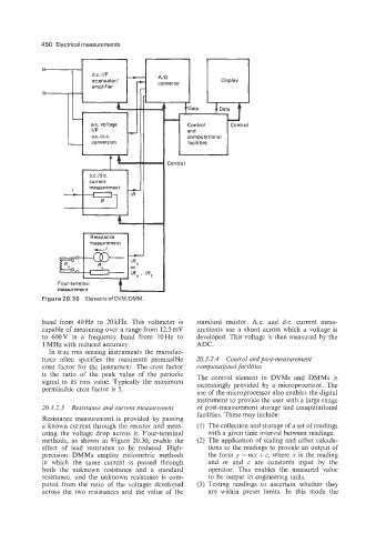
Figure 20.30 Elementsof DVMIDMM.
band from 40Hz to 20kHz. This voltmeter is standard resistor. A.c. and d.c. current meas-
capable of measuring over a range from 12.5 mV urements use a shunt across which a voltage is
to 600V in a frequency band from lOHz to developed. This voltage is then measured by the
1 MHz with reduced accuracy. ADC.
In true rms sensing instruments the manufac-
turer often specifies the maximum permissible 20.3.2.4 Control and post-measurement
crest factor for the instrument. The crest factor computational facilities
is the ratio of the peak value of the periodic The control element in DVMs and DMMs is
signal to its rms value. Typically the maximum increasingly provided by a microprocessor. The
permissible crest factor is 5.
use of the microprocessor also enables the digital
instrument to provide the user with a large range
20.3.2.3 Resistance and current measurement of post-measurement storage and computational
facilities. These may include:
Resistance measurement is provided by passing
a known current through the resistor and meas- (1) The collection and storage of a set of readings
uring the voltage drop across it. Four-terminal with a given time interval between readings.
methods, as shown in Figure 20.30, enable the (2) The application of scaling and offset calcula-
effect of lead resistance to be reduced. High- tions to the readings to provide an output of
precision DMMs employ ratiometric methods the form y = mx + c, where x is the reading
in which the same current is passed through and m and c are constants input by the
both the unknown resistance and a standard operator. This enables the measured value
resistance, and the unknown resistance is com- to be output in engineering units.
puted from the ratio of the voltages developed (3) Testing readings to ascertain whether they
across the two resistances and the value of the are within preset limits. In this mode the