
Page 471 - Instrumentation Reference Book 3E
P. 471
454 Electrical measurements
Table 20.7 Continued
Additional notes Battery operated with LCD LED display LED display
display Intelligent functions include: Intelligent functions include:
Also provides conductance scaling and offsetting, ratio, scaling and
measurement and percentage deviation, low- offsetting, digital filtering,
continuity testing hi-pass, max-min, filtering, statistics, limits, time: real
averaging, and data or elapsed, history file
logging with 1500 numeric
RS232 and IEEE-488 readings or 500 readings
interfaces with time and channel
True rms option available mode
RS232 and IEEE-488
interfaces
where Tis the period of the waveform and thus A
p,? 2.rr lo sin (wt + $6) . dt R
7T/W
Therefore P is given by
vi
.
P = - cos $6
2
The rms voltage, V, is given by
v
"=z
and the rms current, I, is given by power
factor
v~=v;+v;+2vBvccos$
\'l
Thus the average power dissipated by the net-
work is given by Leading
P= VIcos4
(cos + is known as the power factor).
(b)
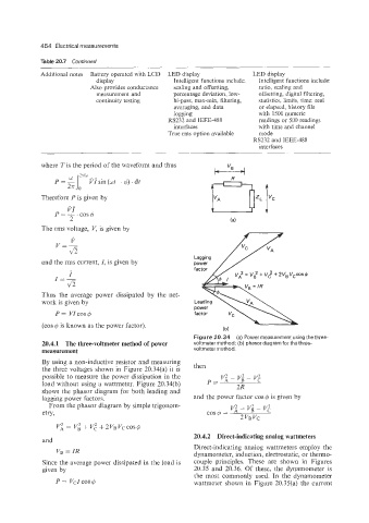
Figure 20.34 (a) Power measurement using the three-
20.4.1 The three-voltmeter method of power voltmeter method; (b) phasor diagram for the three-
measurement voltmeter method.
By using a non-inductive resistor and measuring
the three voltages shown in Figure 20.34(a) it is then
possible to measure the power dissipation in the vi - v; - v;
load without using a wattmeter. Figure 20.34(b) P= 2R
shows the phasor diagram for both leading and
lagging power factors. and the power factor cos $6 is given by
From the phasor diagram by simple trigonom-
etry,
r'i= ~~++'~+2~B~~COS$6
20.4.2 Direct-indicating analog wattmeters
and
Direct-indicating analog wattmeters employ the
VB = IR
dynamometer, induction, electrostatic, or thermo-
Since the average power dissipated in the load is couple principles. These are shown in Figures
given by 20.35 and 20.36. Of these, the dynamometer is
the most commonly used. In the dynamometer
P= VCICOS$6 wattmeter shown in Figure 20.35(a) the current