
Page 475 - Instrumentation Reference Book 3E
P. 475
458 Electrical measurements
and therefore
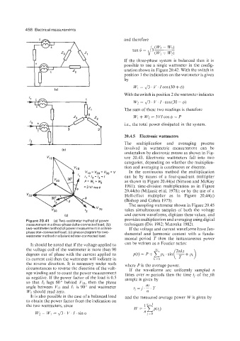
If the three-phase system is balanced then it is
possible to use a single wattmeter in the config-
uration shown in Figure 20.42. With the switch in
position 1 the indication on the wattmeter is given
by
C.Vl = J3 . C' ICOS (30 + 9)
With the switch in position 2 the wattmeter indicates
Wz = 43. V. I. COS(~O - 4)
The sum of these two readings is therefore
+ V'z = 3 COS 4 = P
Le., the total power dissipated in the system.
20.4.5 Electronic wattmeters
The niultiplication and averaging process
involved in wattmetric measurement can be
undertaken by electronic means as shown in Fig-
ure 20.43. Electronic wattmeters fall into two
categories, depending on whether the multiplica-
tion and averaging is continuous or discrete.
=v In the continuous method the multiplication
'30
I can be by means of a four-quadrant multiplier
as shown in Figure 20.44(a) (Simeon and McKay
198 I): time-division multiplication as in Figure
30.44(b) (Miljanic et al. 1978); or by the use of a
"32 Hall-effect multiplier as in Figure 20.44(c)
(Bishop and Cohen 1973).
The sampling wattmeter shown in Figure 20.45
takes simultaneous samples of both the voltage
and current waveforms, digitizes these values, and
(C)
Figure 20.41 (a) Two-wattmeter method of power provides multiplication and averaging using digital
measurement in a three-phase delta-connected load; (b) techniques (Dix 1982: Matouka 1982).
two-wattmeter method of power measurement in a three- If the voltage and current waveforms have fun-
phase star-connected load: (c) phasor diagram for two- damental and harmonic content with a funda-
wattmeter method in a balanced star-connected load.
mental period T then the instantaneous power
It should be noted that if the voltage applied to can be written as a Fourier series:
the voltage coil of the wattmeter is more than 90
degrees out of phase with the current applied to
its current coil then the wattmeter will indicate in
the reverse direction. It is necessary under such where P is the average power.
circumstances to reverse the direction of the volt- If the waveforms are uniformly sampled n
age winding and to count the power measurement times over iiz periods then the time tj of thejth
as negative. If the power factor of the load is 0.5 sample is given by
so that I1 lags 60" behind Vlo, then the phase
angle between VI? and I1 is 90" and wattmeter
Wl should read zero.
It is also possible in the case of a balanced load and the measured average power W is given by
to obtain the power factor from the indication on
the two wattmeters, since 112- I
W? 1V1 = J3. V.I.sino n.
J=o
~