
Page 480 - Instrumentation Reference Book 3E
P. 480
The measi urement of resistance, capacitance, and inductance 463
Gear train If the mutual inductance between the current
A to dials carrying coil and the voltage coil 1 is given by
MI = kl COSS
and if the mutual inductance between the current-
carrying coil and the voltage coil 2 is given by
Mz = kl sin0
then the rest position of the power factor instru-
ment occurs when
Q=d
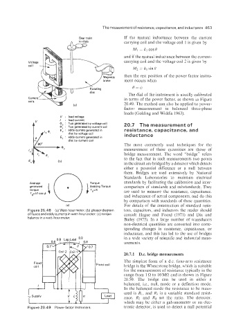
The dial of the instrument is usually calibrated
in terms of the power factor, as shown in Figure
20.49. The method can also be applied to power-
factor measurement in balanced three-phase
loads (Golding and Widdis 1963).
V : loadvoltage
V I : load current
L + : flux generated by voltage coil 20.7 The measurement of
: flux generated by current coil
,, E, : eddy current generated in resistance, capacitance, and
disc by voltage coil
Ei : eddy current generated in inductance
disc by current coil
The most commonly used techniques for the
measurement of these quantities are those of
bridge measurement. The word "bridge" refers
to the fact that in such measurements two points
in the circuit are bridged by a detector which detects
either a potential difference or a null between
them. Bridges are used extensively by National
1 Standards Laboratories to maintain electrical
Average Torque standards by facilitating the calibration and inter-
generated Torque comparison of standards and substandards. They
torque are used to measure the resistance, capacitance.
Tga VI cos $
and inductance of actual components, and do this
by comparison with standards of these quantities.
(C) For details of the construction of standard resis-
Figure 20.48 (a) Watt-hour meter; (b) phasordiagram tors, capacitors. and inductors the reader should
of fluxes and eddy currents in watt-hour meter; (c) torque consult Hague and Foord (1971) and Dix and
balance in a watt-hour meter. Bailey (1975). In a large number of transducers
non-electrical quantities are converted into corre-
sponding changes in resistance, capacitamce, or
inductance, and this has led to the use of bridges
in a wide variety of scientific and industrial meas-
urements.
20.7.1 D.c. bridge measurements
The simplest form of a d.c. four-arm resistance
bridge is the Wheatstone bridge. which is suitable
for the measurement of resistance typically in the
range from 1 !2 to 10 MR and is shown in Figure
20.50. The bridge can be used in either a
balanced, i.e., null, mode or a deflection mode.
In the balanced mode the resistance to be meas-
ured is R1, and R; is a variable standard resist-
ance. R2 and Rd set the ratio. The detector.
which may be either a galvanometer or an elec-
Figure 20.49 Power-factor instrument tronic detector, is used to detect a null potential