
Page 479 - Instrumentation Reference Book 3E
P. 479
462 Electrical measurements
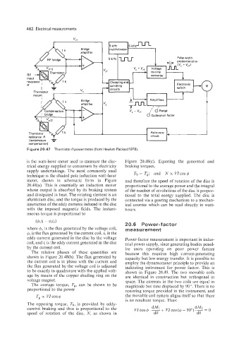
Figure 20.47 Thermistor rf power meter (from Hewlett-Packard 1978)
is the watt-hour meter used to measure the elec- Figure 20.48(c). Equating the generated and
trical energy supplied to consumers by electricity braking torques,
supply undertakings. The most commonly used
technique is the shaded pole induction watt-hour Tb = Ts; and N o( vzCOSf$
meter, shown in schematic form in Figure and therefore the speed of rotation of the disc is
20.48(a). This is essentially an induction motor proportional to the average power and the integral
whose output is absorbed by its braking system of the number of revolutions of the disc is propor-
and dissipated in heat. The rotating element is an tional to the total energy supplied. The disc is
aluminium disc, and the torque is produced by the connected via a gearing mechanism to a mechan-
interaction of the eddy currents induced in the disc ical counter which can be read directly in watt-
with the imposed magnetic fields. The instant- hours.
aneous torque is proportional to
20.6 Power-factor
where dv is the flux generated by the voltage coil, measurement
$i is the flux generated by the current coil. i, is the
eddy current generated in the disc by the voltage Power-factor measurement is important in indus-
coil, and ii is the eddy current generated in the disc trial power supply, since generating bodies penal-
by the current coil. ize users operating on poor power factors
The relative phases of these quantities are because this requires high current-generating
shown in Figure 20.48(b). The flux generated by capacity but low energy transfer. It is possible to
the current coil is in phase with the current and employ the dynamometer principle to provide an
the flux generated by the voltage coil is adjusted indicating instrument for power factor. This is
to be exactly in quadrature with the applied volt- shown in Figure 20.49. The two movable coils
age by means of the copper shading ring on the are identical in construction but orthogonal in
voltage magnet. space. The currents in the two coils are equal in
The average torque, Tg, can be shown to be magnitude but time displaced by 90 '. There is no
proportional to the power restoring torque provided in the instrument, and
Tg K VZcos d the movable coil system aligns itself so that there
is no resultant torque. Thus:
The opposing torque, Tb, is provided by eddy-
current braking and thus is proportional to the
speed of rotation of the disc, N, as shown in