
Page 482 - Instrumentation Reference Book 3E
P. 482
The measurement of resistance, capacitance, and inductance 465
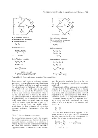
R, is unknown resistance Rq is unknown resistance
RL represents lead resistances RL represents lead resistances
o Connections to R1 o Connections to R,
R4 = Rz R3= R4
BaJance ccmdition. Balance condition:
__-_ __
R1+ RL -R3+ RL
R2 R4
.. R1 =R3 .. R1=R2
Out-of-balance condition: Out - of- balance condition.
R2= R3=R4=R Rz=R~=R~=R
Rl=R(1+6) Ri=R(1+6)
Figure 26.52 Three-lead measurements using awheatstone bridge
Strain gauges and platinum resistance thermo- two, the potential terminals, determine the pre-
meters may be situated at a considerable distance cise length of conductor over which the resistance
from the bridge and the long leads connecting is defined.
the active element to the bridge will have a resist- Measurement of low resistance is undertaken
ance which will vary with temperature. Figure using the Kelvin double bridge shown in Figure
20.52 shows the use of the Wheatstone bridge 20.55(a). R1 is the resistance to be measured and
in three-lead resistance measurement where it RZ is a standard resistance of the same order of
can be seer, that close to balance the effect of magnitude as R1. The link between them which is
the lead resistance and its temperature variation sometimes referred to as the yoke has resistance J..
is approximately self-canceling and that the can- The current through R1 and R? is regulated by R.
celing effect deteriorates the further the bridge R3, R4. r3, r1 are four resistances of which
condition departs from balance. Figure 20.53 either R3 and rj or R4 and 14 are variable, and
shows the use of Smith and Muller bridges for which
to eliminate the lead resistance of a four-lead
platinum resistance thermometer. (See also R3 - J.3
--
~
Chapter I.) R4 ~4
The delta star transformation applied to the
20. 7.1.1 Lou.-resistarice iizenstireiiieiit bridge as shown in Figure 20.55(b) apportions
the yoke resistance between the two sides of the
Contact resistance causes errors in the ineasure- bridge. The balance condhion is given by
ment of low resistance, and therefore in order to
accurately define a resistance it is necessary to RI + ra - R3, ra = J.3 ' J.
___-
.
-
R4
employ the four-terminal technique shown in Fig- R? + 1pc J.4 . J. (1.3 + J.4 + 1.)
ure 10.54. The outer two terminals are used to rc =
supply the current to the resistance. and the inner (P; IJ.4 + 1.)