
Page 484 - Instrumentation Reference Book 3E
P. 484
The measui ,ement of resistance, capacitance, and inductance 467
value and therefore more stable resistances. This
leads to bridges which have larger ratios and
hence reduced sensitivity. By operating the bridge
with R4 as the variable element then as R1 - 130.
Rq + 0.
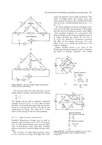
The shunt leakage is made up of leakage resist-
ance across the leads, the terminals of the bridge.
and also across the unknown resistor itself. High-
value standard resistors are constructed with
three terminals. In the bridge arrangement shown
in Figure 20.56(a) Rshl shunts R3 and thus if
R1 >> R3 this method of connection decreases
the effect of the leakage resistance. The only
effect of Rsh2 is to reduce the sensitivity of the
balance condition.
Figure 20.56(b) shows a d.c. form of the
Wagner grounding arrangement used to eliminate
the effect of leakage resistance. The bridge
Rq
R1=- R3Rshl -
R3 + Rsh 1 R4
Figure 20.55 (a) Kelvin double bridge; (b) equivalent
circuit of Kelvin double bridge.
The term involving the yoke resistance I’ can be
made small by making I’ small and also by making
The bridge can be used to measure resistances
typically from 0.1 p0 to 1 R. For high precision
the effect of thermally generated emfs can be elim-
inated by reversing the current in El and R? and
rebalancing the bridge. The value of R1 is then
taken as the average of the two measurements.
Balance conditions:
With detector across AB
20.7.1.2 High-r.esisturice nienstirei~ieizt Rl R,
R2 - R,
Modified Wheatstone bridges can be used to With detector across BC
measure high resistance up to lOI5R. The prob-
lems in such measurements arise from the diff-
culty of producing stable high-value standard
resistors and errors caused by shunt-leakage resist- (b)
ance.
Figure 20.56 (a) Wheatstone bridge forusewith three-
The problem of stable high-resistance values terminal high resistances; (b) d.c. Wagner earthing
can be overcome by using the bridge with lower arrangement.