
Page 489 - Instrumentation Reference Book 3E
P. 489
472 Electrical measurements
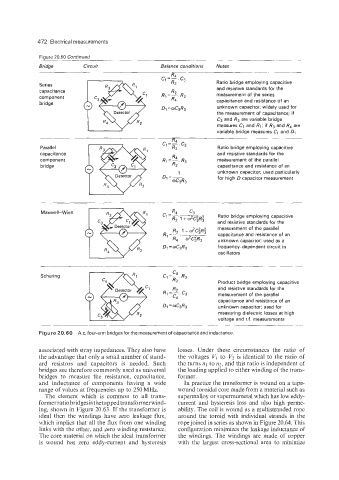
Figure 20.60 Continued
Bridge Circuit Balance conditions Notes
Ratio bridge employing capacitive
Series
capacitance and resistive standards for the
component measurement of the series
bridge capacitance and resistance of an
unknown capacitor; widely used for
the measurement of capacitance; if
C3 and R3 are variable bridge
measures C1 and R1; if R3 and R4 are
variable bridge measures C1 and D1
Parallel Ratio bridge employing capacitive
capacitance and resistive standards for the
component measurement of the parallel
bridge capacitance and resistance of an
unknown capacitor; used particularly
for high D capacitor measurement
Maxwell-Wien R4 c3
C, =-_ R2 , + w2czR; Ratio bridge employing capacitive
and resistive standards for the
measurement of the parallel
R,
+ w2c;R;
R, =-. ___ capacitance and resistance of an
R4 w2C:R3 unknown capacitor; used as a
D1 z~C3R3 frequency-dependent circuit in
oscillators
Ci"-.R3
c4
Schering
R2 Product bridge employing capacitive
R2 and resistive standards for the
R1=-.C3 measurement of the parallel
c4
capacitance and resistance of an
Dq 'mC3R3 unknown capacitor: used for
measuring dielectric losses at high
voltage and r.f. measurements
Figure 20.60 A.c. four-arm bridges for the measurement of capacitance and inductance.
associated with stray impedances. They also have losses. Under these circumstances the ratio of
the advantage that only a small number of stand- the voltages VI to V2 is identical to the ratio of
ard resistors and capacitors is needed. Such the turns 121 to n2, and this ratio is independent of
bridges are therefore commonly used as universal the loading applied to either winding of the trans-
bridges to measure the resistance, capacitance, former.
and inductance of components having a wide In practice the transformer is wound on a tape-
range of values at frequencies up to 250 MHz. wound toroidal core made from a material such as
The element which is common to all trans- supermalloy or supermumetal which has low eddy-
former ratio bridges is thetapped transformerwind- current and hysteresis loss and also high perme-
ing, shown in Figure 20.63. If the transformer is ability. The coil is wound as a multistranded rope
ideal then the windings have zero leakage flux, around the toroid with individual strands in the
which implies that all the flux from one winding rope joined in series as shown in Figure 20.64. This
links with the other, and zero winding resistance. configuration minimizes the leakage inductance of
The core material on which the ideal transformer the windings. The windings are made of copper
is wound has zero eddy-current and hysteresis with the largest cross-sectional area to minimize