
Page 493 - Instrumentation Reference Book 3E
P. 493
476 Electrical measurements
(1971). The current comparator principle can also form a resonant circuit with the current transform-
be extended to enable current comparison to be er and for frequencies below the resonant fre-
made at d.c. (Dix and Bailey 1975). quency the sensitivity of the bridge is dependent
Transformer ratio bridges are often used with on both w, the angular excitation frequency of the
capacitive and inductive displacement trans- bridge, and L,, the self-inductance of the winding
ducers because they are immune to errors caused as shown in Figure 20.71. The dependence of the
by earth-leakage impedances and since they offer sensitivity on w and L, can be reduced at the cost
an easily constructed, stable, and accurately vari- of reduced sensitivity (Neubert 1975).
able current or voltage ratio (Hugill 1983; Neu-
bert 1975).
20.7.4.4 Autobalancing ratio bridges
By employing feedback as shown in Figure 20.72
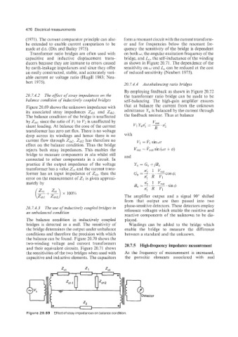
20.7.4.2 The effect of stray iii?pedunces on the the transformer ratio bridge can be made to be
balance condition of inductively coupled bridges self-balancing. The high-gain amplifier ensures
Figure 20.69 shows the unknown impedance with that at balance the current from the unknown
its associated stray impedances Zshl and Zsh?. admittance Y, is balanced by the current through
The balance condition of the bridge is unaffected the feedback resistor. Thus at balance
by Zshl since the ratio of VI to Vz is unaffected by
shunt loading. At balance the core of the current
transformer has zero net flux. There is no voltage
drop across its windings and hence there is no with
current flow through ZShL. Zshl has therefore no V, = PI sinwt
effect on the balance condition. Thus the bridge
rejects both stray impedances. This enables the v,,, = Pout sin (ut + 4)
bridge to measure components in situ whilst still and
connected to other components in a circuit. In
practice if the output impedance of the voltage Yu = Gu +j&
transformer has a value Z,, and the current trans- n' 1 vou,
former has an input impedance of Zct, then the G u-
error on the measurement of 21 is given approxi- n{ R VI
mately by
(%+Z) 100%
x
The amplifier output and a signal 90" shifted
from that output are then passed into two
phase-sensitive detectors. These detectors employ
20.7.4.3 The use of inductively coupled bridges in
an unbalanced condition reference voltages which enable the resistive and
reactive components of the unknown to be dis-
The balance condition in inductively coupled played.
bridges is detected as a null. The sensitivity of Windings can be added to the bridge which
the bridge determines the output under unbalance enable the bridge to measure the difference
conditions and therefore the precision with which between a standard and the unknown.
the balance can be found. Figure 20.70 shows the
two-winding voltage and current transformers 20.7.5 High-frequency impedance measurement
and their equivalent circuits. Figure 20.71 shows
the sensitivities of the two bridges when used with As the frequency of measurement is increased,
capacitive and inductive elements. The capacitors the parasitic elements associated with real
(3etector
Figure 20.69 Effect of stray impedances on balance condition.