
Page 497 - Instrumentation Reference Book 3E
P. 497
480 Electrical measurements
Variable
frequency
source: Tuning
frequency
F Resonance condition 1
r’){etector
1
.
n
r
Resonance
condition
2
IVC2
O=Q =--
u
“in
c=c2
c=c2
Resonance at condition1
inductor L
f-W+ “c2
Resonance at condition 2
Detector
Q=Q =_
C“ plLu PlRU p 2 Vi n
(4
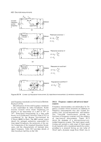
Figure 20.74 Qmeter. (a) Inductance measurement; (b) capacitance measurement; (c) resistance measurement.
and frequency standards can be found in Hewlett- 20.8.1 Frequency counters and universal timer/
Packard (1974). counters
Dissemination of time and frequency standards Frequency measurements are undertaken by fre-
is also undertaken by radio broadcasts. Radio quency counters whose functions (in addition to
stations transmit waves whose frequencies are frequency measurement) may also include fre-
known to an uncertainty of a part in IO” or quency ratio, period measurement, and totaliza-
10”. Time-signal broadcasting on a time scale tion. Universal timer/counters provide the
known as Coordinated Universal Time (UTC) is functions of frequency counters with the addition
coordinated by the Bureau International de of time-interval measurement. Figure 20.75
L‘Heure (BIH) in Paris. The BIH annual report shows the elements of a microprocessor-con-
details the national authorities responsible for trolled frequency counter. The input signal condi-
time-signal broadcasts, the accuracies of the car- tioning unit accepts a wide range of input signal
rier frequencies of the standard frequency broad- levels typically with a maximum sensitivity corres-
casts, and the characteristics of national time- ponding to a sinusoid having an rms value of
signal bradcasts. Table 20.9 provides details of 20 mV and a dynamic range from 20 mV rms to
time broadcast facilities in the UK.